Parts and their functions
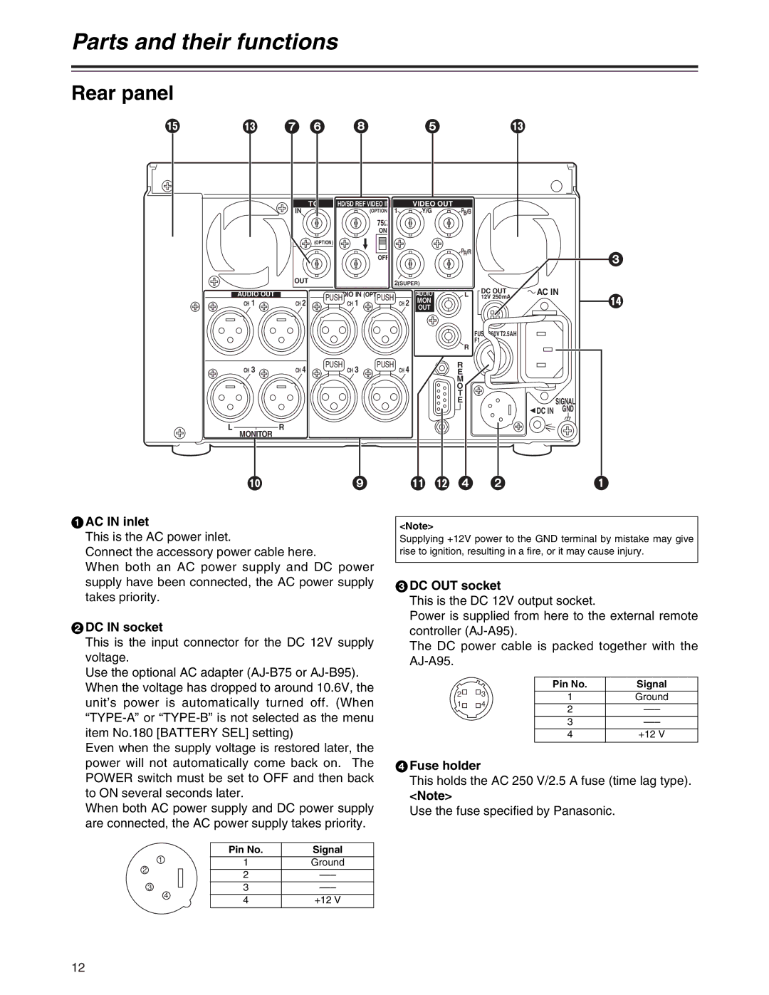
Rear panel
? | = 7 6 8 | 5 | = |
AUDIO OUT
CH 1
TC | HD/SD REF VIDEO IN |
| VIDEO OUT |
|
|
| ||
IN |
|
| (OPTION) | 1 | Y/G | PB/B |
|
|
|
|
| 75Ω |
|
|
|
|
|
|
|
| ON |
|
|
|
|
|
(OPTION) |
|
|
|
|
|
|
| |
|
|
| OFF |
|
| PR/R |
|
|
|
|
|
|
|
|
|
| |
OUT |
|
|
| 2(SUPER) |
|
|
| |
|
|
|
|
|
| AC IN | ||
| AUDIO IN (OPTION) |
| AUDIO | L | DC OUT | |||
CH 2 | PUSH | CH 1 | PUSH | CH 2 | MON |
| 12V 250mA |
|
|
|
|
|
| OUT |
|
|
|
|
|
|
|
|
|
| FUSE 250V T2.5AH |
|
|
|
|
|
|
| R | F1 |
|
|
|
|
|
|
|
|
| |
3
>
CH 3 | CH 4 | PUSH | PUSH | R |
|
CH 3 | CH 4 | E |
| ||
|
|
|
| M |
|
|
|
|
| O |
|
|
|
|
| T |
|
|
|
|
| E | SIGNAL |
|
|
|
| DC IN | GND |
L | R |
|
|
|
|
MONITOR |
|
|
|
|
|
: | 9 ; < 4 2 |
1
1AC IN inlet
This is the AC power inlet.
Connect the accessory power cable here.
When both an AC power supply and DC power supply have been connected, the AC power supply takes priority.
2DC IN socket
This is the input connector for the DC 12V supply voltage.
Use the optional AC adapter
Even when the supply voltage is restored later, the power will not automatically come back on. The POWER switch must be set to OFF and then back to ON several seconds later.
When both AC power supply and DC power supply are connected, the AC power supply takes priority.
|
| Pin No. | Signal |
1 |
| 1 | Ground |
2 |
| 2 | |
|
| ||
3 | 4 | 3 | |
| 4 | +12 V | |
|
|
<Note>
Supplying +12V power to the GND terminal by mistake may give rise to ignition, resulting in a fire, or it may cause injury.
3DC OUT socket
This is the DC 12V output socket.
Power is supplied from here to the external remote controller
The DC power cable is packed together with the
2 | 3 | Pin No. | Signal |
1 | Ground | ||
1 | 4 | 2 | |
|
| ||
|
| 3 | |
|
| 4 | +12 V |
4Fuse holder
This holds the AC 250 V/2.5 A fuse (time lag type).
<Note>
Use the fuse specified by Panasonic.
12