Setup menus
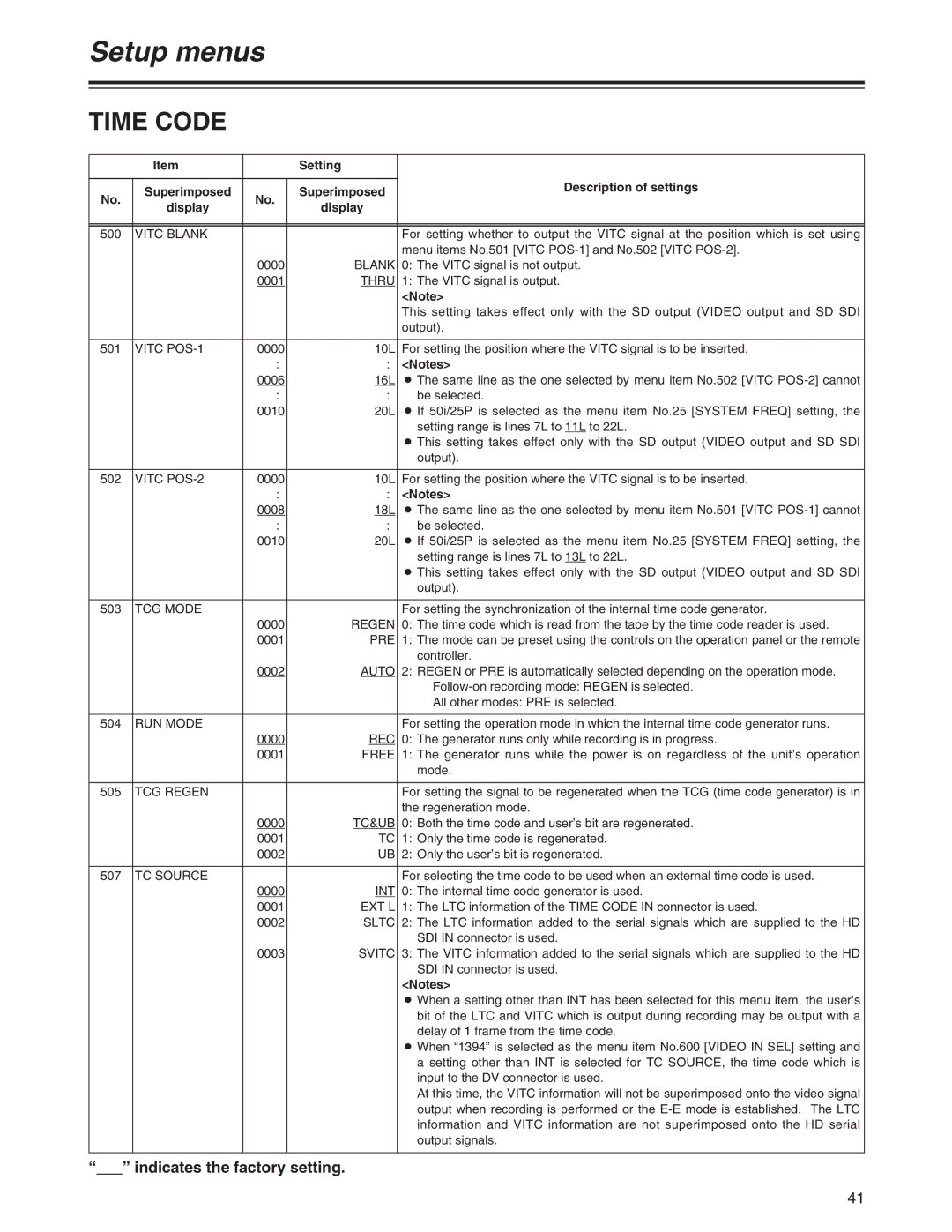
TIME CODE
| Item |
| Setting |
| |
|
|
|
| Description of settings | |
No. | Superimposed | No. | Superimposed | ||
| |||||
display | display |
| |||
|
|
| |||
|
|
|
|
| |
|
|
|
|
| |
500 | VITC BLANK |
|
| For setting whether to output the VITC signal at the position which is set using | |
|
|
|
| menu items No.501 [VITC | |
|
| 0000 | BLANK | 0: The VITC signal is not output. | |
|
| 0001 | THRU | 1: The VITC signal is output. | |
|
|
|
| <Note> | |
|
|
|
| This setting takes effect only with the SD output (VIDEO output and SD SDI | |
|
|
|
| output). | |
|
|
|
|
| |
501 | VITC | 0000 | 10L | For setting the position where the VITC signal is to be inserted. | |
|
| : | : | <Notes> | |
|
| 0006 | 16L | O The same line as the one selected by menu item No.502 [VITC | |
|
| : | : | be selected. | |
|
| 0010 | 20L | O If 50i/25P is selected as the menu item No.25 [SYSTEM FREQ] setting, the | |
|
|
|
| setting range is lines 7L to 11L to 22L. | |
|
|
|
| O This setting takes effect only with the SD output (VIDEO output and SD SDI | |
|
|
|
| output). | |
|
|
|
|
| |
502 | VITC | 0000 | 10L | For setting the position where the VITC signal is to be inserted. | |
|
| : | : | <Notes> | |
|
| 0008 | 18L | O The same line as the one selected by menu item No.501 [VITC | |
|
| : | : | be selected. | |
|
| 0010 | 20L | O If 50i/25P is selected as the menu item No.25 [SYSTEM FREQ] setting, the | |
|
|
|
| setting range is lines 7L to 13L to 22L. | |
|
|
|
| O This setting takes effect only with the SD output (VIDEO output and SD SDI | |
|
|
|
| output). | |
|
|
|
|
| |
503 | TCG MODE |
|
| For setting the synchronization of the internal time code generator. | |
|
| 0000 | REGEN | 0: The time code which is read from the tape by the time code reader is used. | |
|
| 0001 | PRE | 1: The mode can be preset using the controls on the operation panel or the remote | |
|
|
|
| controller. | |
|
| 0002 | AUTO | 2: REGEN or PRE is automatically selected depending on the operation mode. | |
|
|
|
| ||
|
|
|
| All other modes: PRE is selected. | |
|
|
|
|
| |
504 | RUN MODE |
|
| For setting the operation mode in which the internal time code generator runs. | |
|
| 0000 | REC | 0: The generator runs only while recording is in progress. | |
|
| 0001 | FREE | 1: The generator runs while the power is on regardless of the unit’s operation | |
|
|
|
| mode. | |
|
|
|
|
| |
505 | TCG REGEN |
|
| For setting the signal to be regenerated when the TCG (time code generator) is in | |
|
|
|
| the regeneration mode. | |
|
| 0000 | TC&UB | 0: Both the time code and user’s bit are regenerated. | |
|
| 0001 | TC | 1: Only the time code is regenerated. | |
|
| 0002 | UB | 2: Only the user’s bit is regenerated. | |
|
|
|
|
| |
507 | TC SOURCE |
|
| For selecting the time code to be used when an external time code is used. | |
|
| 0000 | INT | 0: The internal time code generator is used. | |
|
| 0001 | EXT L | 1: The LTC information of the TIME CODE IN connector is used. | |
|
| 0002 | SLTC | 2: The LTC information added to the serial signals which are supplied to the HD | |
|
|
|
| SDI IN connector is used. | |
|
| 0003 | SVITC | 3: The VITC information added to the serial signals which are supplied to the HD | |
|
|
|
| SDI IN connector is used. | |
|
|
|
| <Notes> | |
|
|
|
| O When a setting other than INT has been selected for this menu item, the user’s | |
|
|
|
| bit of the LTC and VITC which is output during recording may be output with a | |
|
|
|
| delay of 1 frame from the time code. | |
|
|
|
| O When “1394” is selected as the menu item No.600 [VIDEO IN SEL] setting and | |
|
|
|
| a setting other than INT is selected for TC SOURCE, the time code which is | |
|
|
|
| input to the DV connector is used. | |
|
|
|
| At this time, the VITC information will not be superimposed onto the video signal | |
|
|
|
| output when recording is performed or the | |
|
|
|
| information and VITC information are not superimposed onto the HD serial | |
|
|
|
| output signals. | |
|
|
|
|
|
“” indicates the factory setting.
41