Operating Instructions
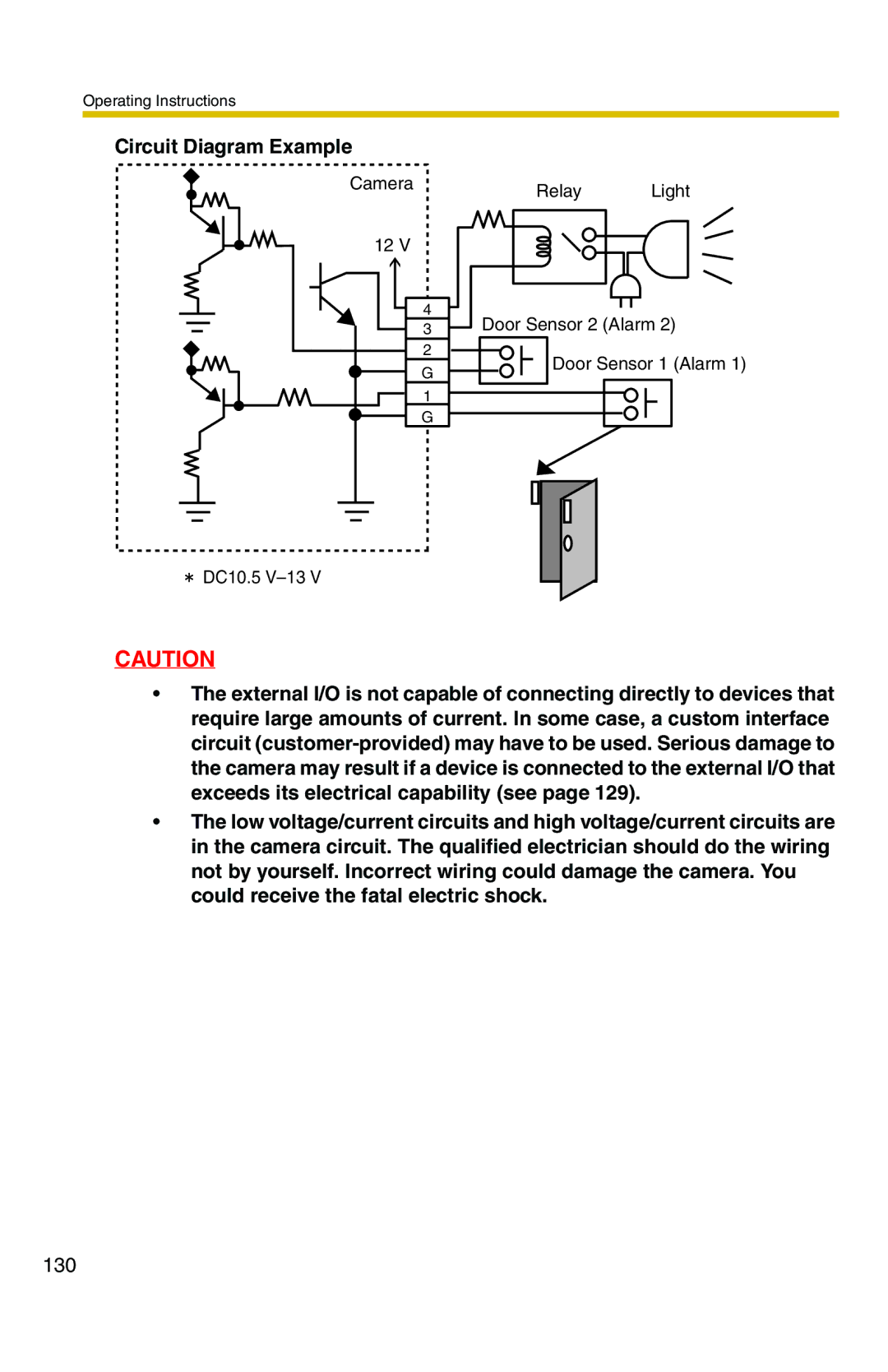
Circuit Diagram Example
Camera
12 V
4
3
2
G
1
G
![]() DC10.5
DC10.5
Relay Light
Door Sensor 2 (Alarm 2)
Door Sensor 1 (Alarm 1)
CAUTION
•The external I/O is not capable of connecting directly to devices that require large amounts of current. In some case, a custom interface circuit
•The low voltage/current circuits and high voltage/current circuits are in the camera circuit. The qualified electrician should do the wiring not by yourself. Incorrect wiring could damage the camera. You could receive the fatal electric shock.
130