[Connections and Settings in Torque Control Mode]
|
|
|
|
|
|
|
|
|
|
|
|
|
|
|
|
|
|
|
|
|
|
|
| Default setting is shown by [ ] | ||
Parameter | Parameter Name |
| Setting |
|
|
|
|
|
|
|
|
| Function/Description | |||||||||||||
No. |
| range |
|
|
|
|
|
|
|
|
| |||||||||||||||
|
|
|
|
|
|
|
|
|
|
|
|
|
|
|
|
|
|
|
|
|
|
|
|
| ||
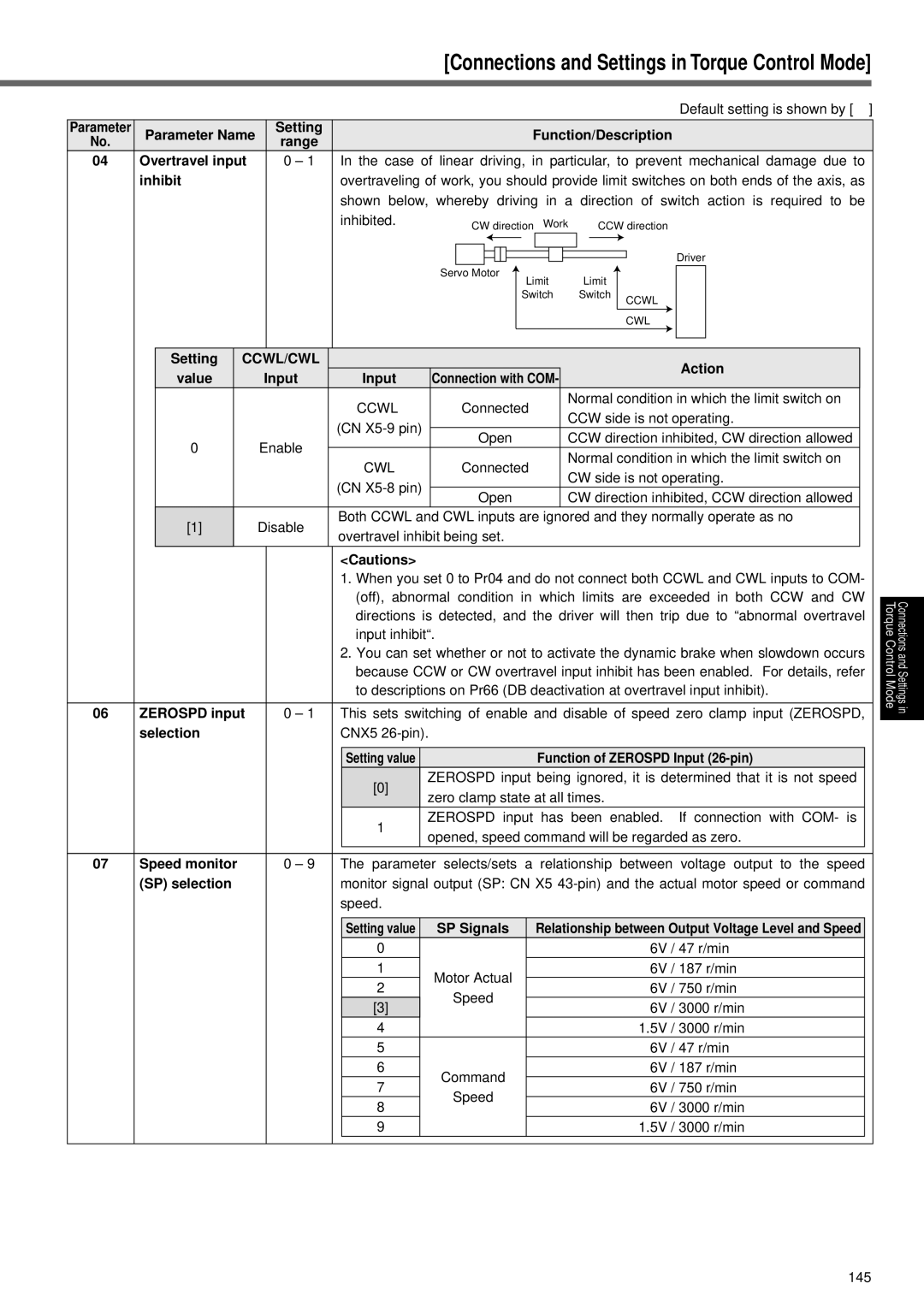
04 | Overtravel input |
| 0 – 1 | In the case of linear driving, in particular, to prevent mechanical damage due to | ||||||||||||||||||||||
| inhibit |
|
| overtraveling of work, you should provide limit switches on both ends of the axis, as | ||||||||||||||||||||||
|
|
|
|
|
| shown below, whereby driving in a direction of switch action is required to be | ||||||||||||||||||||
|
|
|
|
|
| inhibited. |
| CW direction Work |
| CCW direction | ||||||||||||||||
|
|
|
|
|
|
|
|
|
|
|
|
|
|
|
|
|
|
|
|
|
|
|
| Driver | ||
|
|
|
|
|
|
|
|
|
|
|
|
|
|
|
|
|
|
|
|
|
|
|
| |||
|
|
|
|
|
|
|
|
|
|
|
|
|
|
|
|
|
|
|
|
|
| |||||
|
|
|
|
|
|
|
|
|
|
|
|
|
|
|
|
|
|
|
|
|
|
|
|
|
|
|
|
|
|
|
|
|
| Servo Motor |
| Limit |
| Limit |
|
|
|
|
|
| |||||||||
|
|
|
|
|
|
|
|
|
|
|
|
|
|
|
|
|
|
|
|
|
| |||||
|
|
|
|
|
|
|
|
|
|
|
|
|
|
| Switch |
| Switch | CCWL |
|
|
| |||||
|
|
|
|
|
|
|
|
|
|
|
|
|
|
|
|
|
|
|
|
|
|
|
| |||
|
|
|
|
|
|
|
|
|
|
|
|
|
|
|
|
|
|
|
|
|
|
|
|
|
| |
|
|
|
|
|
|
|
|
|
|
|
|
|
|
|
|
|
|
|
|
| CWL |
|
|
| ||
|
|
|
|
|
|
|
|
|
|
|
|
|
|
|
|
|
|
|
|
|
|
|
|
|
| |
|
|
|
|
|
|
|
|
|
|
|
|
|
|
|
|
|
|
|
|
|
|
|
|
|
|
|
|
|
|
|
|
|
|
|
|
|
|
|
|
|
|
|
|
|
|
|
|
|
|
|
|
| |
|
| Setting | CCWL/CWL |
|
|
|
|
|
|
|
|
|
|
|
|
|
|
|
|
|
| Action |
| |||
|
| value |
| Input | Input | Connection with COM- |
|
|
|
|
|
|
| |||||||||||||
|
|
|
|
|
|
|
|
|
|
|
| |||||||||||||||
|
|
|
|
|
| CCWL |
| Connected | Normal condition in which the limit switch on |
| ||||||||||||||||
|
|
|
|
|
|
| CCW side is not operating. |
| ||||||||||||||||||
|
|
|
|
|
| (CN |
|
|
|
|
|
|
|
|
|
|
|
| ||||||||
|
| 0 |
| Enable |
| Open | CCW direction inhibited, CW direction allowed |
| ||||||||||||||||||
|
|
|
|
|
| |||||||||||||||||||||
|
|
| CWL |
| Connected | Normal condition in which the limit switch on |
| |||||||||||||||||||
|
|
|
|
|
|
|
| |||||||||||||||||||
|
|
|
|
|
|
| CW side is not operating. |
| ||||||||||||||||||
|
|
|
|
|
| (CN |
|
|
|
|
|
|
|
|
|
|
|
| ||||||||
|
|
|
|
|
|
| Open | CW direction inhibited, CCW direction allowed |
| |||||||||||||||||
|
|
|
|
|
|
|
|
| ||||||||||||||||||
|
| [1] |
| Disable | Both CCWL and CWL inputs are ignored and they normally operate as no |
| ||||||||||||||||||||
|
|
| overtravel inhibit being set. |
|
|
|
|
|
|
|
|
| ||||||||||||||
|
|
|
|
|
|
|
|
|
|
|
|
|
|
| ||||||||||||
<Cautions>
1.When you set 0 to Pr04 and do not connect both CCWL and CWL inputs to COM- (off), abnormal condition in which limits are exceeded in both CCW and CW directions is detected, and the driver will then trip due to “abnormal overtravel input inhibit“.
2.You can set whether or not to activate the dynamic brake when slowdown occurs because CCW or CW overtravel input inhibit has been enabled. For details, refer to descriptions on Pr66 (DB deactivation at overtravel input inhibit).
06 | ZEROSPD input | 0 – 1 This sets switching of enable and disable of speed zero clamp input (ZEROSPD, | |||||||
| selection | CNX5 |
|
|
|
| |||
|
|
|
|
|
|
| |||
|
|
|
| Setting value |
|
| Function of ZEROSPD Input |
| |
|
|
|
| [0] | ZEROSPD input being ignored, it is determined that it is not speed |
| |||
|
|
| zero clamp state at all times. |
|
| ||||
|
|
|
|
|
|
| |||
|
|
|
| 1 | ZEROSPD input has been enabled. If connection with COM- is |
| |||
|
|
| opened, speed command will be regarded as zero. |
| |||||
|
|
|
|
|
| ||||
|
|
|
|
|
|
|
|
|
|
07 | Speed monitor | 0 – 9 The parameter | selects/sets | a relationship between voltage output to the speed | |||||
| (SP) selection | monitor signal output (SP: CN X5 | |||||||
|
| speed. |
|
|
|
| |||
|
|
|
|
|
|
|
|
| |
|
|
|
| Setting value |
| SP Signals | Relationship between Output Voltage Level and Speed |
| |
|
|
|
| 0 |
|
| 6V | / 47 r/min |
|
|
|
|
| 1 | Motor Actual | 6V | / 187 r/min |
| |
|
|
|
| 2 | 6V | / 750 r/min |
| ||
|
|
|
|
| Speed |
| |||
|
|
|
| [3] |
| 6V | / 3000 r/min |
| |
|
|
|
|
|
|
| |||
|
|
|
| 4 |
|
| 1.5V | / 3000 r/min |
|
|
|
|
| 5 |
|
| 6V | / 47 r/min |
|
|
|
|
| 6 |
| Command | 6V | / 187 r/min |
|
|
|
|
| 7 |
| 6V | / 750 r/min |
| |
|
|
|
|
| Speed |
| |||
|
|
|
| 8 |
| 6V | / 3000 r/min |
| |
|
|
|
|
|
|
| |||
|
|
|
| 9 |
|
| 1.5V | / 3000 r/min |
|
Torque Control Mode
Connections and Settings in
145