[Connections and Settings in Torque Control Mode]
Output Circuit
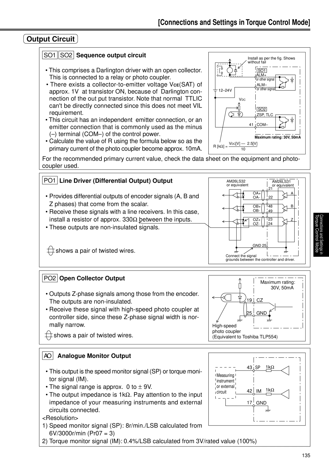
SO1 
 SO2 Sequence output circuit
•This comprises a Darlington driver with an open collector. This is connected to a relay or photo coupler.
•There exists a
•This circuit has an independent emitter connection, or an emitter connection that is commonly used as the minus
•Calculate the value of R using the formula below so as the primary current of the photo coupler become approx. 10mA.
Install as per the fig. Shows without fail
| SO1 |
| ALM+ |
| or other signal |
| ALM– |
or other signal | |
| |
| VDC |
SO2
ZSP, TLC
41 COM–
Maximum rating: 30V, 50mA
R [kΩ] = VDC[V] — 2.5[V] 10
For the recommended primary current value, check the data sheet on the equipment and photo- coupler used.
PO1 Line Driver (Differential Output) Output
•Provides differential outputs of encoder signals (A, B and Z phases) that come from the scalar.
•Receive these signals with a line receivers. In this case, install a resistor of approx. 330Ω between the inputs.
•These outputs are
![]() shows a pair of twisted wires.
shows a pair of twisted wires.
AM26LS32 | AM26LS31 | |
or equivalent | or equivalent | |
| 21 |
|
OA+ | 22 | A |
OA- |
| |
OB+ | 48 | B |
OB- | 49 |
|
OZ+ | 23 | Z |
OZ- | 24 |
|
GND 25
Connect the signal
grounds between the controller and driver.
Torque Control Mode
Connections and Settings in
PO2 Open Collector Output
•Outputs
•Receive these signal with
![]() shows a pair of twisted wires.
shows a pair of twisted wires.
| Maximum rating: |
| 30V, 50mA |
19 | CZ |
25 | GND |
| |
photo coupler |
|
(Equivalent to Toshiba TLP554) | |
AO
Analogue Monitor Output
• This output is the speed monitor signal (SP) or torque moni- | Measuring |
|
|
|
| |
|
|
|
| |||
|
|
|
| |||
tor signal (IM). |
|
|
|
| ||
instrument |
|
|
|
| ||
• The signal range is approx. 0 to ± 9V. | or external | 42 | IM | 1k | Ω | |
• The output impedance is 1kΩ. Pay attention to the input | circuit | |||||
| ||||||
|
|
|
|
| ||
impedance of your measuring instruments and external |
| 17 | GND | |||
circuits connected. |
|
|
|
|
| |
<Resolution> |
|
|
|
|
| |
1)Speed monitor signal (SP): 8r/min./LSB calculated from 6V/3000r/min (Pr07 = 3)
2)Torque monitor signal (IM): 0.4%/LSB calculated from 3V/rated value (100%)
135