[Connections and Settings in Torque Control Mode]
|
|
|
|
|
|
|
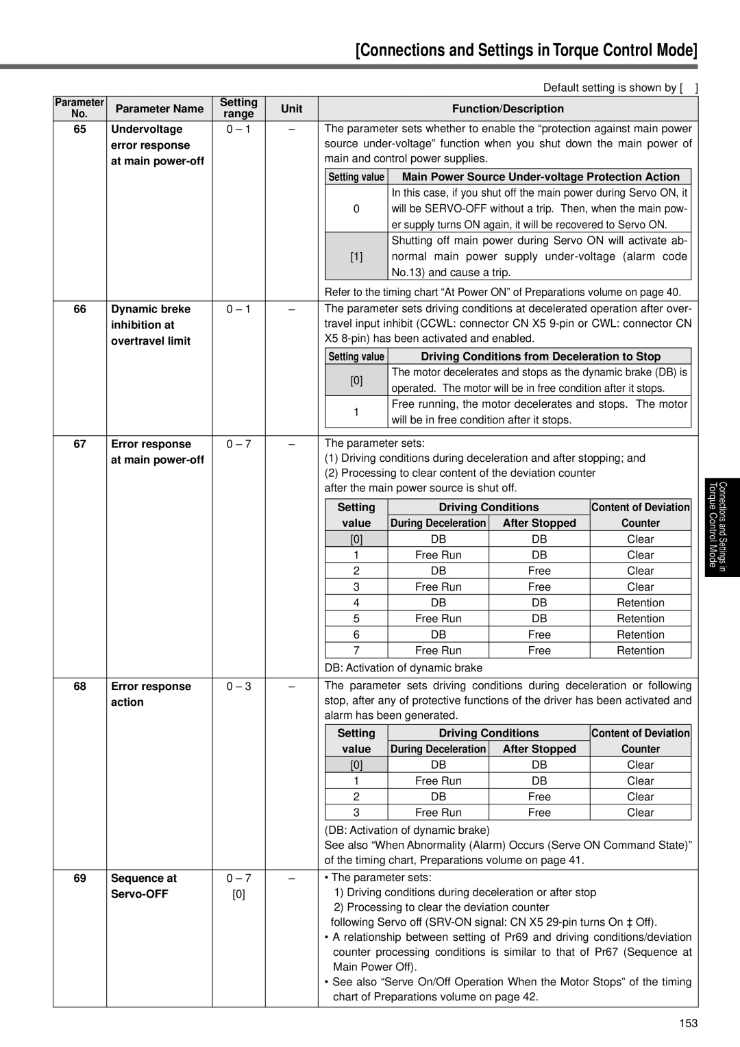
| Default setting is shown by [ ] | ||
Parameter | Parameter Name | Setting | Unit |
|
| Function/Description |
|
| ||
No. | range |
|
|
|
| |||||
|
|
|
|
|
|
|
|
| ||
65 | Undervoltage | 0 – 1 | – | The parameter sets whether to enable the “protection against main power | ||||||
| error response |
|
| source | ||||||
| at main |
|
| main and control power supplies. |
|
|
| |||
|
|
|
|
| Setting value | Main Power Source |
| |||
|
|
|
|
|
| In this case, if you shut off the main power during Servo ON, it |
| |||
|
|
|
|
| 0 | will be |
| |||
|
|
|
|
|
| er supply turns ON again, it will be recovered to Servo ON. |
| |||
|
|
|
|
|
| Shutting off main power during Servo ON will activate ab- |
| |||
|
|
|
|
| [1] | normal main power supply |
| |||
|
|
|
|
|
| No.13) and cause a trip. |
|
| ||
|
|
|
| Refer to the timing chart “At Power ON” of Preparations volume on page 40. | ||||||
|
|
|
|
|
|
|
|
|
| |
66 | Dynamic breke | 0 – 1 | – | The parameter sets driving conditions at decelerated operation after over- | ||||||
| inhibition at |
|
| travel input inhibit (CCWL: connector CN X5 | ||||||
| overtravel limit |
|
| X5 |
|
| ||||
|
|
|
|
| Setting value | Driving Conditions from Deceleration to Stop |
| |||
|
|
|
|
| [0] | The motor decelerates and stops as the dynamic brake (DB) is |
| |||
|
|
|
|
| operated. The motor will be in free condition after it stops. |
| ||||
|
|
|
|
|
|
| ||||
|
|
|
|
| 1 | Free running, the motor decelerates and stops. The motor |
| |||
|
|
|
|
| will be in free condition after it stops. |
|
| |||
|
|
|
|
|
|
|
| |||
|
|
|
|
|
|
|
|
| ||
67 | Error response | 0 – 7 | – | The parameter sets: |
|
|
| |||
| at main |
|
| (1) Driving conditions during deceleration and after stopping; and | ||||||
|
|
|
| (2) Processing to clear content of the deviation counter | ||||||
|
|
|
| after the main power source is shut off. |
|
| ||||
|
|
|
|
|
|
|
|
| ||
|
|
|
|
| Setting | Driving Conditions | Content of Deviation |
| ||
|
|
|
|
| value | During Deceleration |
| After Stopped | Counter |
|
|
|
|
|
| [0] | DB |
| DB | Clear |
|
|
|
|
|
| 1 | Free Run |
| DB | Clear |
|
|
|
|
|
| 2 | DB |
| Free | Clear |
|
|
|
|
|
| 3 | Free Run |
| Free | Clear |
|
|
|
|
|
| 4 | DB |
| DB | Retention |
|
|
|
|
|
| 5 | Free Run |
| DB | Retention |
|
|
|
|
|
| 6 | DB |
| Free | Retention |
|
|
|
|
|
| 7 | Free Run |
| Free | Retention |
|
|
|
|
| DB: Activation of dynamic brake |
|
|
| |||
|
|
|
|
| ||||||
68 | Error response | 0 – 3 | – | The parameter sets driving conditions during deceleration or following | ||||||
| action |
|
| stop, after any of protective functions of the driver has been activated and | ||||||
|
|
|
| alarm has been generated. |
|
|
| |||
|
|
|
|
|
|
|
| |||
|
|
|
|
| Setting | Driving Conditions | Content of Deviation |
| ||
|
|
|
|
| value | During Deceleration |
| After Stopped | Counter |
|
|
|
|
|
| [0] | DB |
| DB | Clear |
|
|
|
|
|
| 1 | Free Run |
| DB | Clear |
|
|
|
|
|
| 2 | DB |
| Free | Clear |
|
|
|
|
|
| 3 | Free Run |
| Free | Clear |
|
|
|
|
| (DB: Activation of dynamic brake) |
|
|
| |||
|
|
|
| See also “When Abnormality (Alarm) Occurs (Serve ON Command State)” | ||||||
|
|
|
| of the timing chart, Preparations volume on page 41. |
|
| ||||
|
|
|
|
|
|
|
| |||
69 | Sequence at | 0 – 7 | – | • The parameter sets: |
|
|
| |||
|
| [0] |
|
| 1) Driving conditions during deceleration or after stop | |||||
|
|
|
|
| 2) Processing to clear the deviation counter |
|
| |||
|
|
|
|
| following Servo off | |||||
|
|
|
| • A relationship between setting of Pr69 and driving conditions/deviation | ||||||
|
|
|
|
| counter processing conditions is similar to that of Pr67 (Sequence at | |||||
|
|
|
|
| Main Power Off). |
|
|
| ||
|
|
|
| • See also “Serve On/Off Operation When the Motor Stops” of the timing | ||||||
|
|
|
|
| chart of Preparations volume on page 42. |
|
| |||
|
|
|
|
|
|
|
|
|
|
|
Torque Control Mode
Connections and Settings in
153