CN X5 Connector
Interface Circuit
Input Circuit
SI SI Connecting to sequence input signals
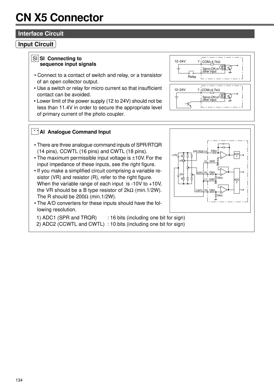
•Connect to a contact of switch and relay, or a transistor of an open collector output.
•Use a switch or relay for micro current so that insufficient contact can be avoided.
•Lower limit of the power supply (12 to 24V) should not be less than 11.4V in order to secure the appropriate level of primary current of the photo coupler.
7 | COM+4.7kΩ | |
|
| |
|
| other input |
| Relay |
|
7 | COM+4.7kΩ | |
|
| |
|
| other input |
AI AI Analogue Command Input
•There are three analogue command inputs of SPR/RTQR (14 pins), CCWTL (16 pins) and CWTL (18 pins).
•The maximum permissible input voltage is ±10V. For the input impedance of these inputs, see the right figure.
•If you make a simplified circuit comprising a variable re- sistor (VR) and resistor (R), refer to the right figure.
When the variable range of each input is
•The A/D converters for these inputs should have the fol- lowing resolution.
|
| SPR/TRQR 14 | 20kΩ |
| |
+12V |
|
|
| - | ADC |
R |
|
|
| ||
|
| + | 1 | ||
|
|
| |||
| VR | 15 | GND |
|
|
|
| CCWTL 16 | 10kΩ | - |
|
| + |
| |||
|
|
|
| ||
| R | 17 | GND | 10kΩ | ADC |
|
|
|
|
| 2 |
|
| CWTL 18 | 10kΩ | - |
|
|
| + |
| ||
|
|
|
|
| |
|
|
|
| 10kΩ |
|
1) ADC1 | (SPR and TRQR) | : 16 bits (including one bit for sign) |
2) ADC2 | (CCWTL and CWTL) | : 10 bits (including one bit for sign) |
134
