Using the serial connector
The serial connector which is on the side terminal board of the projector conforms to the
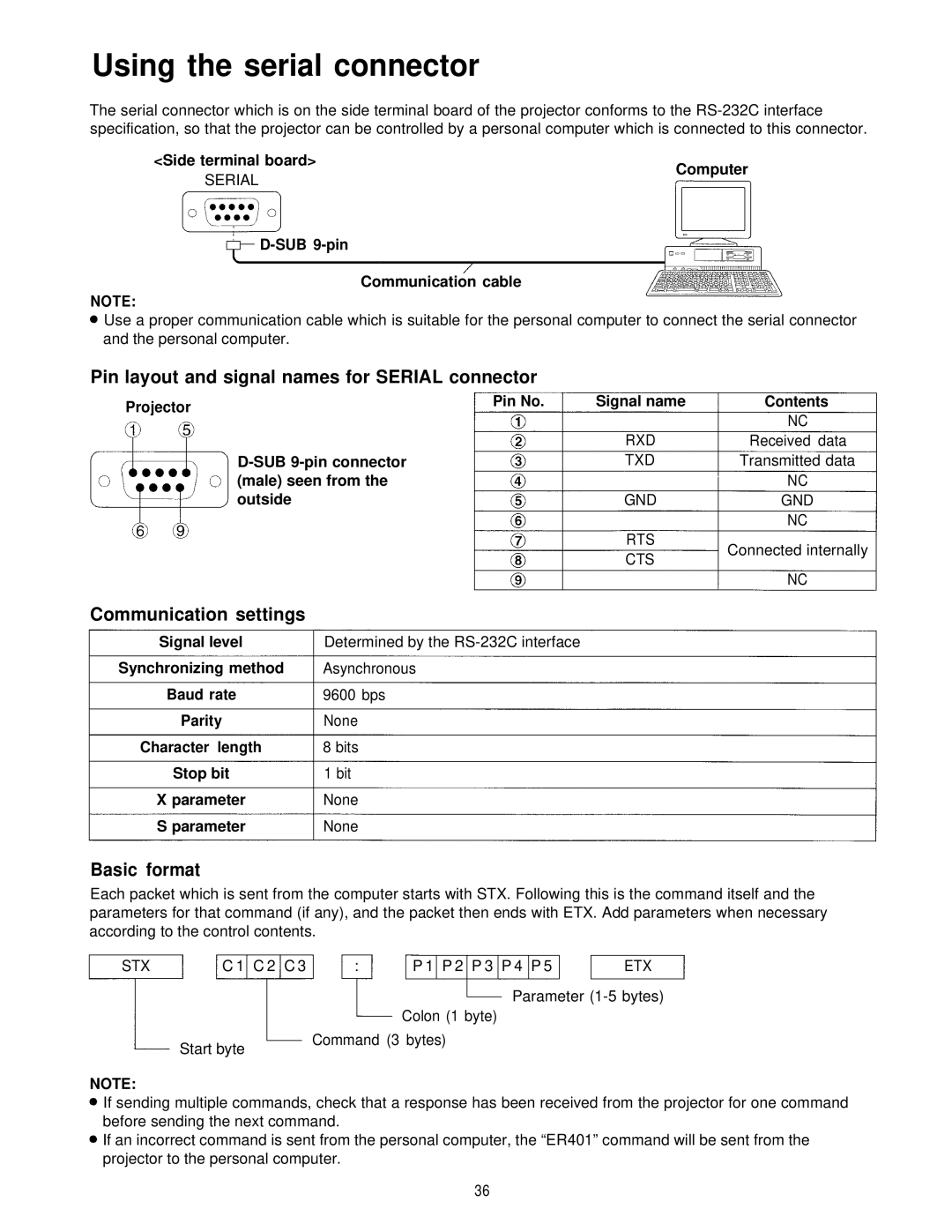
<Side terminal board>
SERIAL
Computer
D-SUB 9-pin
Communication cable
NOTE:
Use a proper communication cable which is suitable for the personal computer to connect the serial connector and the personal computer.
Pin layout and signal names for SERIAL connector
Projector | Pin No. | Signal name | Contents |
|
| NC | |
|
|
| |
|
| RXD | Received data |
| TXD | Transmitted data | |
| (male) seen from the |
| NC |
| outside | GND | GND |
|
|
| NC |
|
| RTS | Connected internally |
|
| CTS | |
|
|
| |
|
|
| NC |
Communication settings
Signal level | Determined by the |
Synchronizing method | Asynchronous |
Baud rate | 9600 bps |
Parity | None |
Character length | 8 bits |
Stop bit | 1 bit |
X parameter | None |
S parameter | None |
Basic format
Each packet which is sent from the computer starts with STX. Following this is the command itself and the parameters for that command (if any), and the packet then ends with ETX. Add parameters when necessary according to the control contents.
STX | C 1 C 2 C 3 | : | P 1 P 2 P 3 P 4 P 5 | ETX |
Start byte
NOTE:
Parameter
Colon (1 byte)
Command (3 bytes)
If sending multiple commands, check that a response has been received from the projector for one command before sending the next command.
If an incorrect command is sent from the personal computer, the “ER401” command will be sent from the projector to the personal computer.
36