• Connection with PS·Data systems
This is an example of connection when the unit is used together with the PS·Data devices.
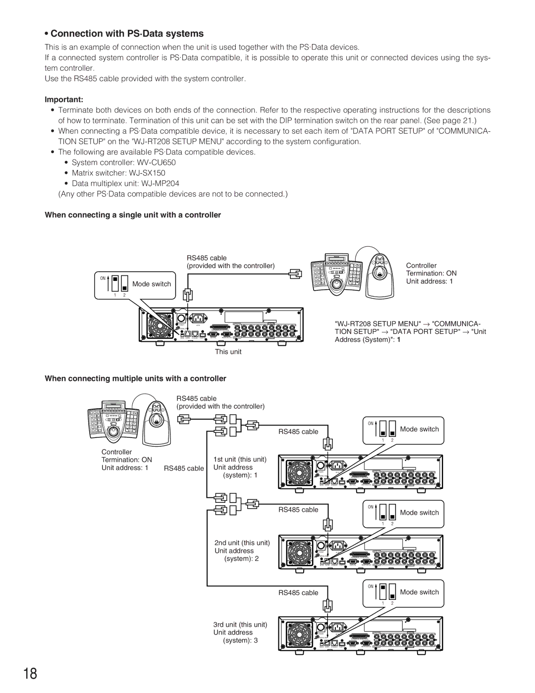
If a connected system controller is PS·Data compatible, it is possible to operate this unit or connected devices using the sys- tem controller.
Use the RS485 cable provided with the system controller.
Important:
•Terminate both devices on both ends of the connection. Refer to the respective operating instructions for the descriptions of how to terminate. Termination of this unit can be set with the DIP termination switch on the rear panel. (See page 21.)
•When connecting a PS·Data compatible device, it is necessary to set each item of "DATA PORT SETUP" of "COMMUNICA- TION SETUP" on the
•The following are available PS·Data compatible devices.
•System controller:
•Matrix switcher:
•Data multiplex unit:
(Any other PS·Data compatible devices are not to be connected.)
When connecting a single unit with a controller
RS485 cable
(provided with the controller)
ON ![]()
Mode switch
1 2
ON |
|
|
|
|
|
|
|
|
|
|
|
OFF |
|
|
|
|
|
|
|
|
|
|
|
POWER | AC IN |
|
| AUDIO OUT | 2 | 3 | 4 | AUDIO IN | 6 | 7 | 8 |
|
| 1 | 5 | ||||||||
SIGNAL GND |
| TERMINAL/CONTROL |
|
|
|
|
|
|
|
| |
|
|
|
|
|
|
|
|
|
| ||
|
| SERIAL | MONITOR(VGA) | 1 | 2 | 3 | 4 | 5 | 6 | 7 | 8 |
MODE DATA | VIDEO OUT |
|
|
| VIDEO IN |
|
|
| |||
This unit
|
| A | B | Controller |
|
|
|
| |
4 | 5 | 6 |
| Termination: ON |
1 | 2 | 3 |
|
|
7 | 8 | 9 |
| Unit address: 1 |
| 0 |
|
|
When connecting multiple units with a controller
RS485 cable
(provided with the controller)
A ![]() B
B
1 | 2 | 3 |
4 | 5 | 6 |
7 | 8 | 9 |
| 0 |
|
Controller |
|
Termination: ON |
|
Unit address: 1 | RS485 cable |
RS485 cable
1st unit (this unit) Unit address
ON
OFF
ON ![]()
Mode switch
1 2
(system): 1
POWER
SIGNAL GND
AC IN
AUDIO OUT
|
|
|
| AUDIO IN |
|
|
|
1 | 2 | 3 | 4 | 5 | 6 | 7 | 8 |
TERMINAL/CONTROL
|
| MODE DATA | SERIAL | MONITOR(VGA) VIDEO OUT |
|
|
|
|
|
|
|
|
|
|
|
|
|
|
|
|
|
|
|
|
1 | 2 | 3 | 4 | 5 | 6 | 7 | 8 |
|
|
|
| VIDEO IN |
|
|
|
RS485 cable
ON ![]()
1 2
Mode switch
2nd unit (this unit) | ON |
|
|
|
|
|
|
|
|
|
Unit address | OFF |
|
|
|
|
|
|
|
|
|
| AC IN | 1 | 2 | 3 | 4 | 5 | 6 | 7 | 8 | |
| POWER |
| AUDIO OUT |
|
|
| AUDIO IN |
|
|
|
|
|
|
|
|
|
|
|
| ||
(system): 2 | SIGNAL GND |
| TERMINAL/CONTROL |
|
|
|
|
|
|
|
|
|
|
|
|
|
|
|
| ||
|
|
| 1 | 2 | 3 | 4 | 5 | 6 | 7 | 8 |
| MODE DATA | SERIAL MONITOR(VGA) VIDEO OUT |
|
|
| VIDEO IN |
|
|
| |
| RS485 cable |
| ON |
| Mode switch | |||||
|
|
|
| |||||||
|
|
| 1 | 2 |
|
|
|
|
|
|
3rd unit (this unit) Unit address
(system): 3
ON |
|
|
|
|
|
|
|
|
|
|
|
OFF |
|
|
|
|
|
|
|
|
|
|
|
POWER | AC IN |
|
| AUDIO OUT | 2 | 3 | 4 | AUDIO IN | 6 | 7 | 8 |
|
| 1 | 5 | ||||||||
SIGNAL GND |
| TERMINAL/CONTROL |
|
|
|
|
|
|
|
| |
|
|
|
|
|
|
|
|
|
| ||
|
| SERIAL | MONITOR(VGA) | 1 | 2 | 3 | 4 | 5 | 6 | 7 | 8 |
MODE DATA | VIDEO OUT |
|
|
| VIDEO IN |
|
|
| |||
18