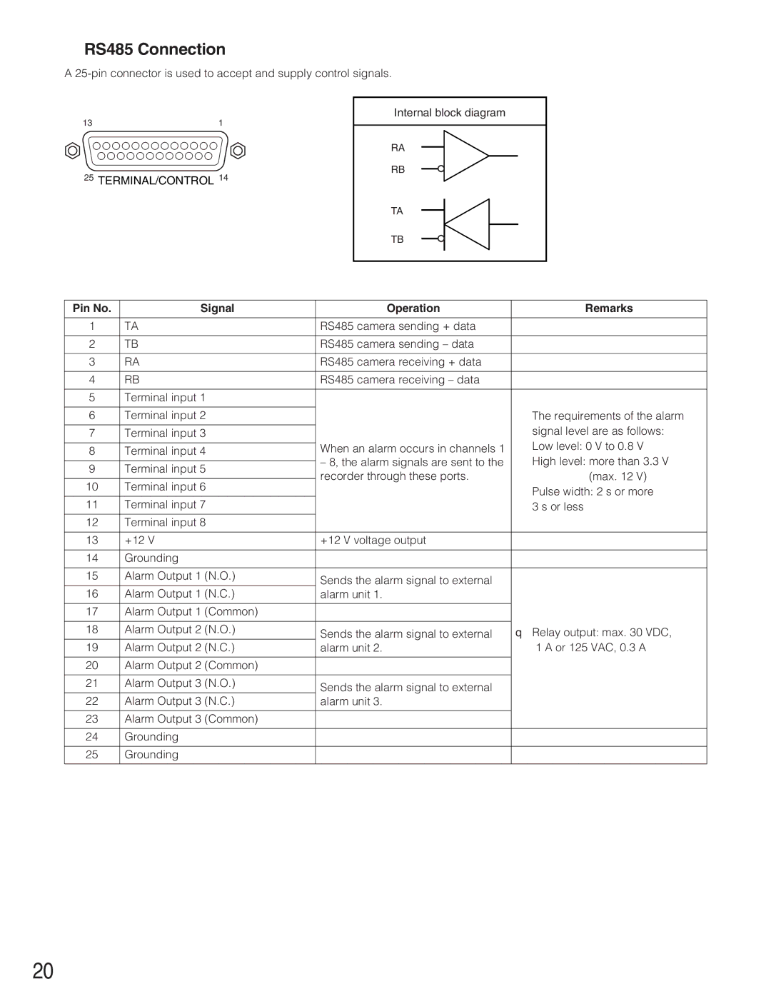
■RS485 Connection
A
Internal block diagram
13 | 1 |
RA
RB
25TERMINAL/CONTROL 14
TA
TB
Pin No. | Signal | Operation | Remarks | |
|
|
|
| |
1 | TA | RS485 camera sending + data |
| |
|
|
|
| |
2 | TB | RS485 camera sending – data |
| |
|
|
|
| |
3 | RA | RS485 camera receiving + data |
| |
|
|
|
| |
4 | RB | RS485 camera receiving – data |
| |
|
|
|
| |
5 | Terminal input 1 |
|
| |
|
|
|
| |
6 | Terminal input 2 |
| The requirements of the alarm | |
|
|
| signal level are as follows: | |
7 | Terminal input 3 |
| ||
|
| When an alarm occurs in channels 1 | Low level: 0 V to 0.8 V | |
8 | Terminal input 4 | |||
|
| – 8, the alarm signals are sent to the | High level: more than 3.3 V | |
9 | Terminal input 5 | |||
recorder through these ports. | (max. 12 V) | |||
|
| |||
10 | Terminal input 6 | |||
| Pulse width: 2 s or more | |||
|
|
| ||
11 | Terminal input 7 |
| 3 s or less | |
12 | Terminal input 8 |
|
| |
|
|
|
| |
13 | +12 V | +12 V voltage output |
| |
|
|
|
| |
14 | Grounding |
|
| |
|
|
|
| |
15 | Alarm Output 1 (N.O.) | Sends the alarm signal to external |
| |
|
|
| ||
16 | Alarm Output 1 (N.C.) | alarm unit 1. |
| |
|
|
|
| |
17 | Alarm Output 1 (Common) |
|
| |
|
|
|
| |
18 | Alarm Output 2 (N.O.) | Sends the alarm signal to external | q Relay output: max. 30 VDC, | |
19 | Alarm Output 2 (N.C.) | alarm unit 2. | 1 A or 125 VAC, 0.3 A | |
|
|
|
| |
20 | Alarm Output 2 (Common) |
|
| |
|
|
|
| |
21 | Alarm Output 3 (N.O.) | Sends the alarm signal to external |
| |
|
|
| ||
22 | Alarm Output 3 (N.C.) | alarm unit 3. |
| |
|
|
|
| |
23 | Alarm Output 3 (Common) |
|
| |
|
|
|
| |
24 | Grounding |
|
| |
|
|
|
| |
25 | Grounding |
|
| |
|
|
|
|
20
