CONNECTIONS
A. WV-CL920 (120 V AC 60Hz)
1.Plug the AC power cord (supplied as standard accessory) into the AC Inlet Socket.
2.Connect the AC power cord to a 120 V AC 60 Hz
outlet.
Notes:
•Connect the power cord firmly.
•The power cord should be long enough for pan- ning and tilting.
If the cable is too short, the power cord plug may be pulled off the camera when the camera pans or tilts.
B.WV-CL924 (12 V DC/24 V AC)
The
Resistance of copper wire [at 20°C (68°F)]
Copper wire | #24 | #22 | #20 | #18 |
size (AWG) | (0.22 mm2) | (0.33 mm2) | (0.52 mm2) | (0.83 mm2) |
|
|
|
|
|
Resistance | 0.078 | 0.050 | 0.030 | 0.018 |
Ω /m |
|
|
|
|
|
|
|
|
|
Resistance | 0.026 | 0.017 | 0.010 | 0.006 |
Ω /ft |
|
|
|
|
|
|
|
|
|
•Calculation of maximum cable length between camera and power supply.
10.8V DC ≤ VA − (R x 0.42 x L) ≤ 16 V DC
L : Cable length (m)
R : Resistance of copper wire (Ω /m)
VA : DC output voltage of power supply unit
L standard = | VA − | 12 | (m) |
|
| ||
|
| ||
| 0.42 x R | ||
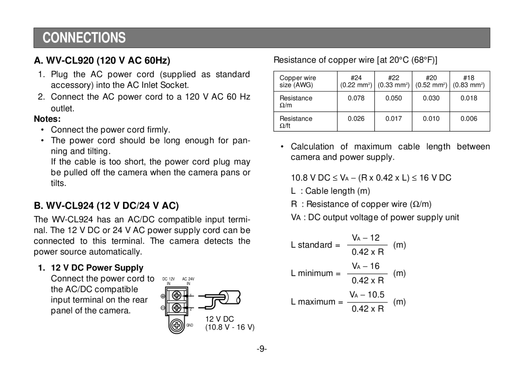
1.12 V DC Power Supply Connect the power cord to the AC/DC compatible input terminal on the rear panel of the camera.
DC 12V | AC 24V |
IN | IN |
| 1 |
| 2 |
| GND |
12 V DC
(10.8 V - 16 V)
L minimum = | VA − | 16 | (m) |
|
| ||
| 0.42 x R | ||
L maximum = | VA − | 10.5 | (m) |
|
| ||
|
| ||
0.42 x R