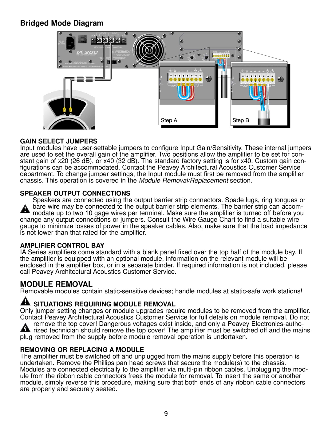
Bridged Mode Diagram
GAIN SELECT JUMPERS
Input modules have
SPEAKER OUTPUT CONNECTIONS
Speakers are connected using the output barrier strip connectors. Spade lugs, ring tongues or bare wire may be connected to the output barrier strip elements. The barrier strip can accom- modate up to two 10 gage wires per terminal. Make sure the amplifier is turned off before you
change any output connections or jumpers. Consult the Wire Gauge Chart to find a suitable wire gauge to minimize losses of power in the speaker cables. Also, make sure that the load impedance is not lower than that rated for the amplifier.
AMPLIFIER CONTROL BAY
IA Series amplifiers come standard with a blank panel fixed over the top half of the module bay. If the amplifier is equipped with an optional module, information on the relevant module will be enclosed in the amplifier box, or in a separate binder. If required information is not included, please call Peavey Architectural Acoustics Customer Service.
MODULE REMOVAL
Removable modules contain
 SITUATIONS REQUIRING MODULE REMOVAL
Only jumper setting changes or module upgrades require modules to be removed from the amplifier. Contact Peavey Architectural Acoustics Customer Service for full details on module removal. Do not
remove the top cover! Dangerous voltages exist inside, and only a Peavey
plug removed from the supply before module removal operation is undertaken.
REMOVING OR REPLACING A MODULE
The amplifier must be switched off and unplugged from the mains supply before this operation is undertaken. Remove the Phillips pan head screws that secure the module(s) to the chassis. Modules are connected electrically to the amplifier via
9