16 C1570M-E (4/07)
BASIC HARDWARE CONNECTIONS

CM9700-CC1 CONNECTION

Use the 16-pin terminal block (included with the CM9700MDD-EVS) for the RS-422 serial connection (Pelco P protocol) between the
CM9700MDD-EVS and the CM9700-CC1.
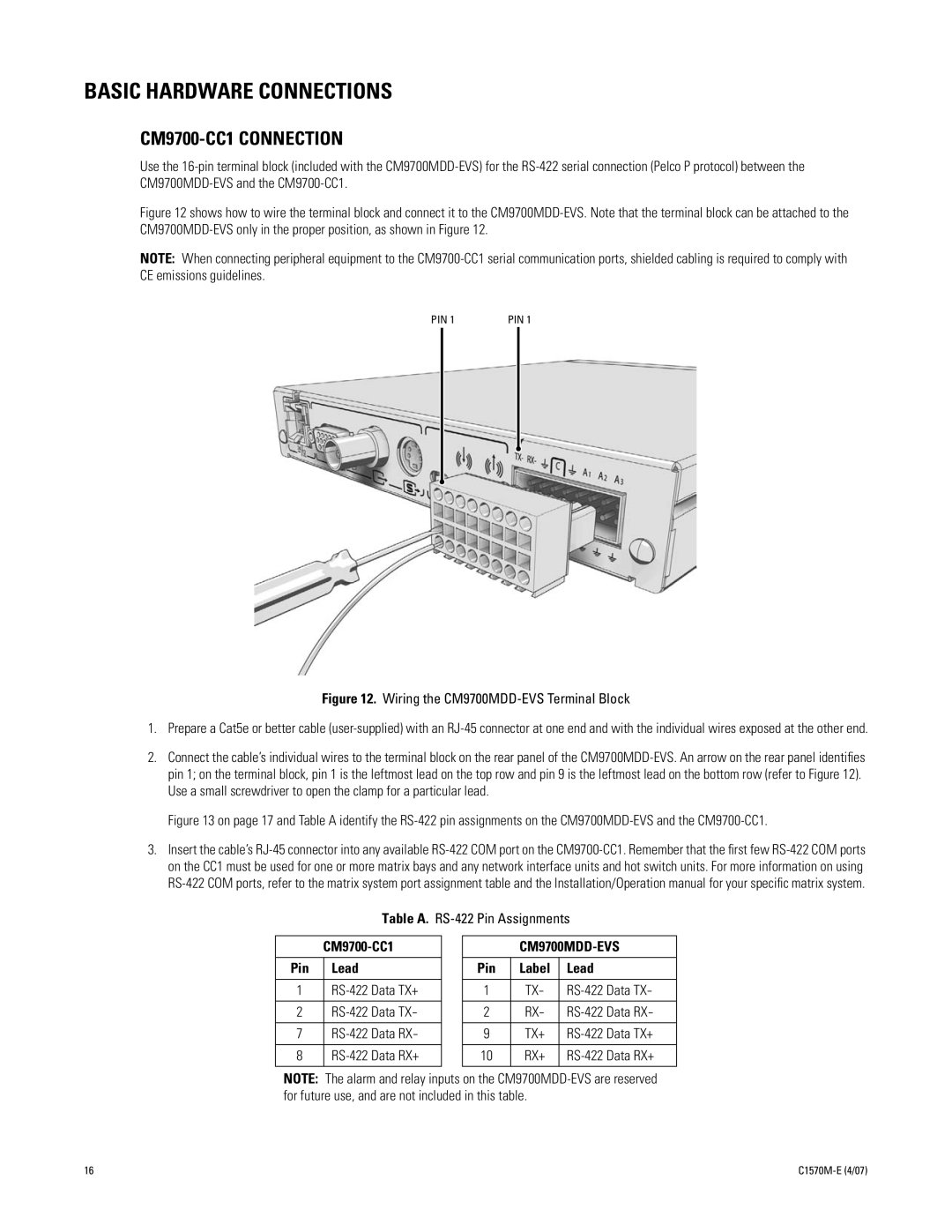
Figure 12 shows how to wire the terminal block and connect it to the CM9700MDD-EVS. Note that the terminal block can be attached to the
CM9700MDD-EVS only in the proper position, as shown in Figure 12.
NOTE:
When connecting peripheral equipment to the CM9700-CC1 serial communication ports, shielded cabling is required to comply with
CE emissions guidelines.
Figure 12.
Wiring the CM9700MDD-EVS Terminal Block
1. Prepare a Cat5e or better cable (user-supplied) with an RJ-45 connector at one end and with the individual wires exposed at the other end.
2. Connect the cable’s individual wires to the terminal block on the rear panel of the CM9700MDD-EVS. An arrow on the rear panel identifies
pin 1; on the terminal block, pin 1 is the leftmost lead on the top row and pin 9 is the leftmost lead on the bottom row (refer to Figure 12).
Use a small screwdriver to open the clamp for a particular lead.
Figure 13 on page 17 and Table A identify the RS-422 pin assignments on the CM9700MDD-EVS and the CM9700-CC1.
3. Insert the cable’s RJ-45 connector into any available RS-422 COM port on the CM9700-CC1. Remember that the first few RS-422 COM ports
on the CC1 must be used for one or more matrix bays and any network interface units and hot switch units. For more information on using
RS-422 COM ports, refer to the matrix system port assignment table and the Installation/Operation manual for your specific matrix system.
Table A.
RS-422 Pin Assignments
CM9700-CC1 CM9700MDD-EVS
Pin Lead Pin Label Lead
1 RS-422 Data TX+ 1 TX
-
RS-422 Data TX
-
2 RS-422 Data TX
-
2RX
-
RS-422 Data RX
-
7 RS-422 Data RX
-
9 TX+ RS-422 Data TX+
8 RS-422 Data RX+ 10 RX+ RS-422 Data RX+
NOTE:
The alarm and relay inputs on the CM9700MDD-EVS are reserved
for future use, and are not included in this table.
PIN 1 PIN 1