|
|
|
|
| VGA MONITOR |
|
|
|
|
|
|
|
|
| |||
|
|
|
|
|
|
|
|
|
|
|
|
|
|
|
|
|
|
|
|
|
|
|
|
|
|
|
PIN 1
PRINTER | COM 1 | COM 2 |
PIN 8
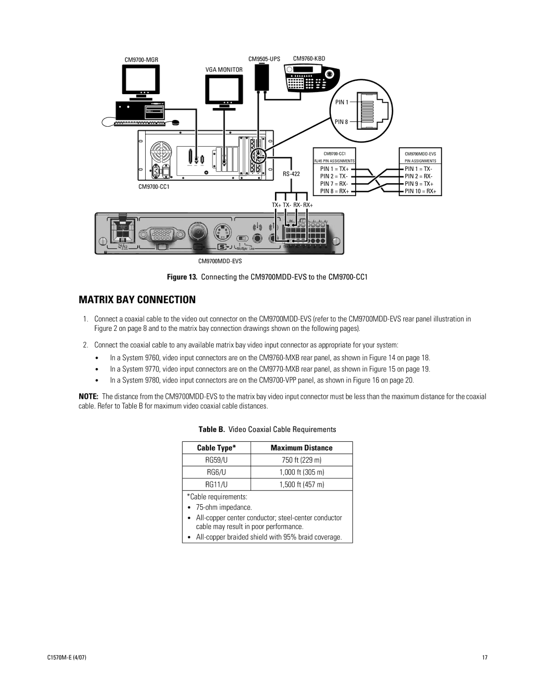
RJ45 PIN ASSIGNMENTS
PIN 1 = TX+
PIN 2 = TX-
PIN 7 = RX-
PIN 8 = RX+
PIN ASSIGNMENTS
PIN 1 = TX- PIN 2 = RX- PIN 9 = TX+ PIN 10 = RX+
TX+ TX- RX- RX+
Figure 13. Connecting the CM9700MDD-EVS to the CM9700-CC1
MATRIX BAY CONNECTION
1.Connect a coaxial cable to the video out connector on the
2.Connect the coaxial cable to any available matrix bay video input connector as appropriate for your system:
•In a System 9760, video input connectors are on the
•In a System 9770, video input connectors are on the
•In a System 9780, video input connectors are on the
NOTE: The distance from the
Table B. Video Coaxial Cable Requirements
Cable Type* | Maximum Distance |
|
|
RG59/U | 750 ft (229 m) |
|
|
RG6/U | 1,000 ft (305 m) |
|
|
RG11/U | 1,500 ft (457 m) |
|
|
*Cable requirements:
•
•
•All-copper braided shield with 95% braid coverage.
17 |