Figure 22. Number of Devices Page
Select the number of CM9700MDD-EVS units. Remember that one matrix bay input must be available for each CM9700MDD-EVS, so the number of units cannot exceed the number of available inputs on the matrix bay.
5.Click Next. The Port Configuration page opens, with the number of the first available port in the Host Port field. You can select a different port number; note however that it is strongly recommended that you use the default baud rate and parity settings, which are provided.
NOTE: All
Figure 23. Port Configuration Page
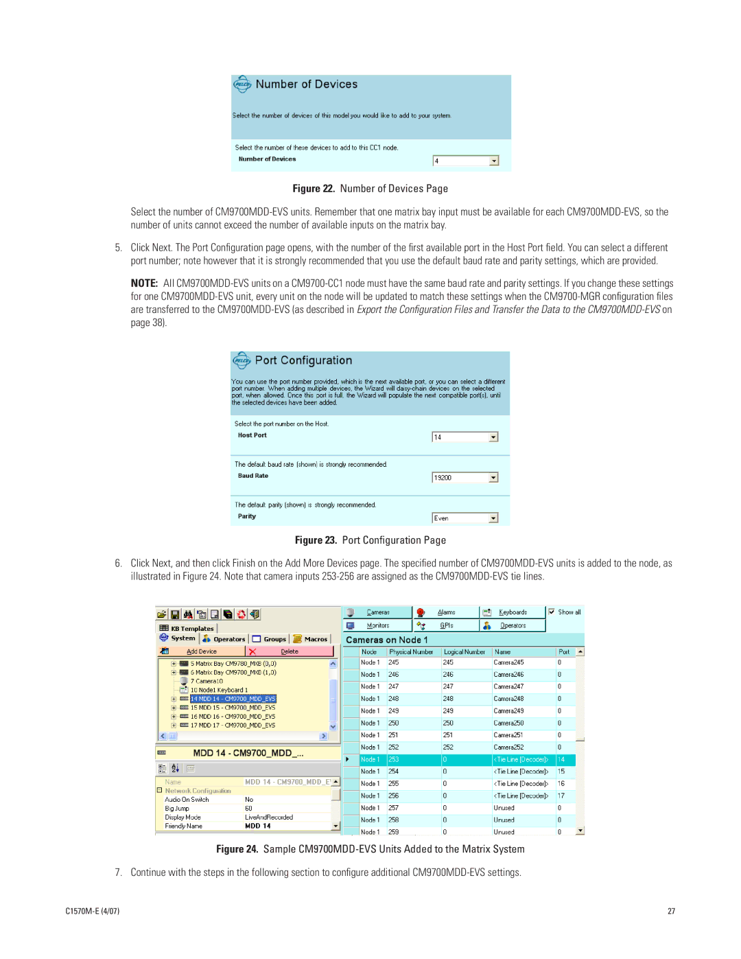
6.Click Next, and then click Finish on the Add More Devices page. The specified number of
Figure 24. Sample CM9700MDD-EVS Units Added to the Matrix System
7. Continue with the steps in the following section to configure additional CM9700MDD-EVS settings.
27 |