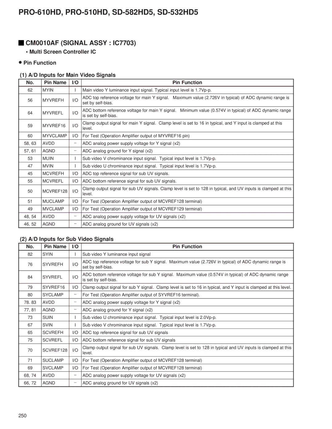
PRO-510HD, PRO-610HD specifications
The Pioneer PRO-510HD and PRO-610HD are two advanced professional display monitors that exemplify cutting-edge technology in the realm of high-definition visual solutions. Designed for various applications, including broadcasting, live events, and video production, these monitors provide exceptional image quality and versatile features.One of the standout characteristics of both models is their high-resolution display capabilities. The PRO-510HD boasts a 51-inch screen size with an impressive resolution of 1920 x 1080 pixels, ensuring sharp and vibrant images that meet the demands of professional users. The larger PRO-610HD features a 61-inch screen size with the same high-definition resolution, allowing for an immersive viewing experience.
These monitors leverage advanced LCD technology to deliver remarkable color accuracy and consistent brightness. With a wide color gamut, users can expect true-to-life colors, making these monitors ideal for color-critical applications. The brightness levels of both models reach up to 700 cd/m², ensuring visibility even in brightly lit environments.
Connectivity is a crucial aspect of any professional monitor, and the PRO-510HD and PRO-610HD are equipped with a range of input options. They offer multiple HD-SDI, HDMI, DVI, and analog connections, allowing for seamless integration with various broadcasting and production equipment. This flexibility ensures that users can easily connect their devices without the need for additional converters or adapters.
Another significant feature of these monitors is the built-in waveform and vector scope displays. These tools are essential for ensuring proper exposure and color balance, providing users with real-time monitoring of their video signals. The monitors also support various aspect ratios, making it easy to adjust the display according to specific project requirements.
Durability is key for professional equipment, and both the PRO-510HD and PRO-610HD are constructed with robust materials, ensuring longevity even in demanding environments. The monitors are designed for continuous operation, making them reliable for long hours of use whether in studios or on location.
In conclusion, the Pioneer PRO-510HD and PRO-610HD are powerful tools for professionals who require high-quality displays with advanced features. Their excellent image quality, extensive connectivity options, and integrated monitoring tools make them an attractive choice for anyone involved in video production or broadcasting. With their durable design and user-friendly operation, these monitors stand out as reliable partners in the visual media landscape.
