05Part Names
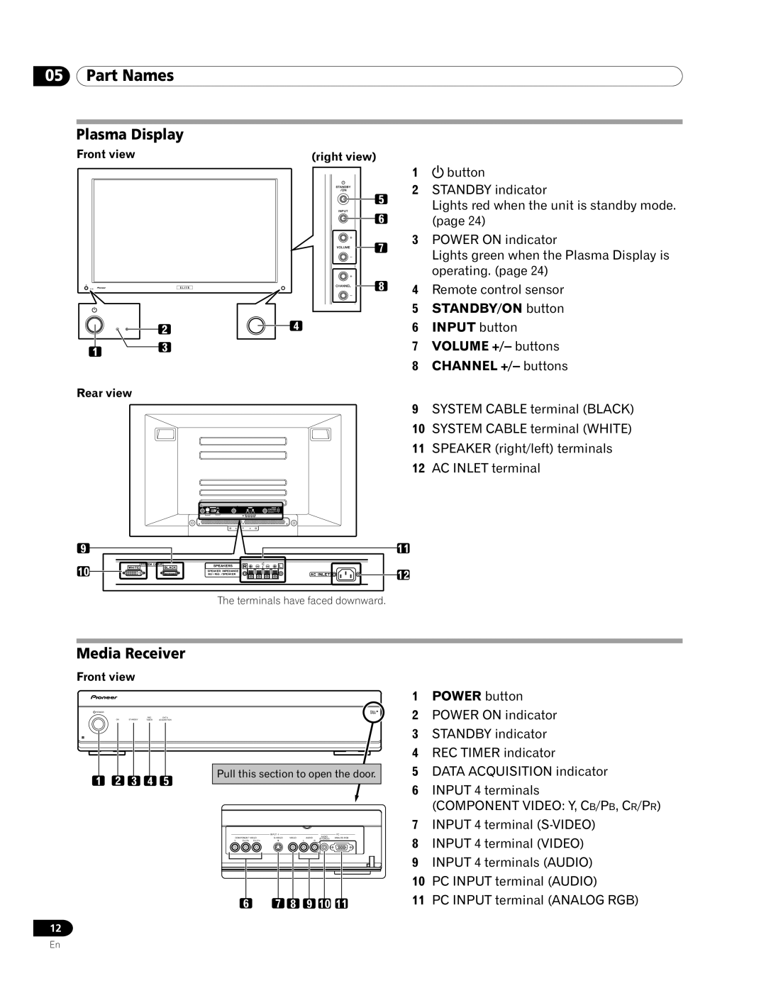
Plasma Display
Front view | (right view) |
5
6
7
8
4
Rear view
1![]() button
button
2STANDBY indicator
Lights red when the unit is standby mode. (page 24)
3POWER ON indicator
Lights green when the Plasma Display is operating. (page 24)
4Remote control sensor
5STANDBY/ON button
6INPUT button
7VOLUME +/– buttons
8CHANNEL +/– buttons
9SYSTEM CABLE terminal (BLACK)
10SYSTEM CABLE terminal (WHITE)
11SPEAKER (right/left) terminals
12AC INLET terminal
9
10
11
12
The terminals have faced downward.
Media Receiver
Front view
POWER
|
| REC | DATA |
ON | STANDBY | TIMER | ACQUISITION |
1 2 3 4 5
Pull this section to open the door.
|
| INPUT 4 |
|
|
|
|
| AUDIO | PC |
|
COMPONENT VIDEO | VIDEO | AUDIO |
| (STEREO) | ANALOG RGB | |||||
Y | CB / PB CR / PR |
|
|
| L | R |
|
| ||
1 | POWER button |
2 | POWER ON indicator |
3 | STANDBY indicator |
4 | REC TIMER indicator |
5 | DATA ACQUISITION indicator |
6 | INPUT 4 terminals |
| (COMPONENT VIDEO: Y, CB/PB, CR/PR) |
7 | INPUT 4 terminal |
8 | INPUT 4 terminal (VIDEO) |
9 | INPUT 4 terminals (AUDIO) |
10 | PC INPUT terminal (AUDIO) |
6 | 7 | 8 | 9 | 10 11 |
12
11 PC INPUT terminal (ANALOG RGB) |
En
