SC-37SC-35
Risk of Electric Shock Do not Open
Operating Environment
Information to User
Federal Communications Commission Declaration of Conformity
Important Notice
SC-37 only
Contents
Listening to your system
Using other functions
Playback with Home Media Gallery inputs SC-37 only
Control with Hdmi function
Controlling the rest of your system In case of SC-35
System Setup and Other Setup menus
Advanced Mcacc menu
Additional information
Flow of settings on the receiver
Before you start
Features
Before you start Chapter
Our philosophy
Before you start Checking what’s in the box
Installing the receiver
Loading the batteries
Setting the ‘RF Remote Setup’ to ‘ON’
Before you start Operating range of remote control unit
Pairing the RF adapter and remote control
Tip
Controls and displays
Remote control In case of SC-37
Controls and displays Chapter
Remote control display for RF two-way communications3
Remote control display2
Controls and displays
Mute
RF adapter
LED Setting
Front Rear
Receiver Control buttons Press Receiver first to access
Controls and displays Remote control In case of SC-35
TV Ctrl
Receiver
Display
MULTI-ZONE
Full Band
Sound
Phase Control
Sleep
18 S.RTRV
STANDBY/ON
Controls and displays Front panel
Audio Parameter
Video Parameter
Band
Tuner Edit
Speakers
Home Menu
Connecting your equipment Chapter
Connecting your equipment
Rear panel
SC-37
Connecting the RF adapter
Connecting your equipment
Front panel
Channel surround system Front wide
Channel surround system Front height
Channel surround system & Speaker B connection
Placing the speakers
THX speaker system setup
Other speaker connections
Some tips for improving sound quality
Bare wire connections
Connecting the speakers
Banana plug connections
Standard surround connection
Connecting your equipment Installing your speaker system
Bi-amping your speakers
Bi-wiring your speakers
About the audio connection
Connecting your equipment Selecting the Speaker system
About the video converter
Color and x.v.Color logo are trademarks of Sony Corporation
About HDMI1
Select one
Connecting using Hdmi
DVD player, etc HDMI/DVI-compatible Monitor Select one
Connecting your DVD player with no Hdmi output
Coaxial Optical Analog L
Connecting your TV with no Hdmi input
HDD/DVD recorder, BD recorder, etc
STB
Video OUT
About the WMA9 Pro decoder
Connecting your equipment Connecting other audio components
Turntables only
Connecting AM/FM antennas
Connecting your equipment Connecting additional amplifiers
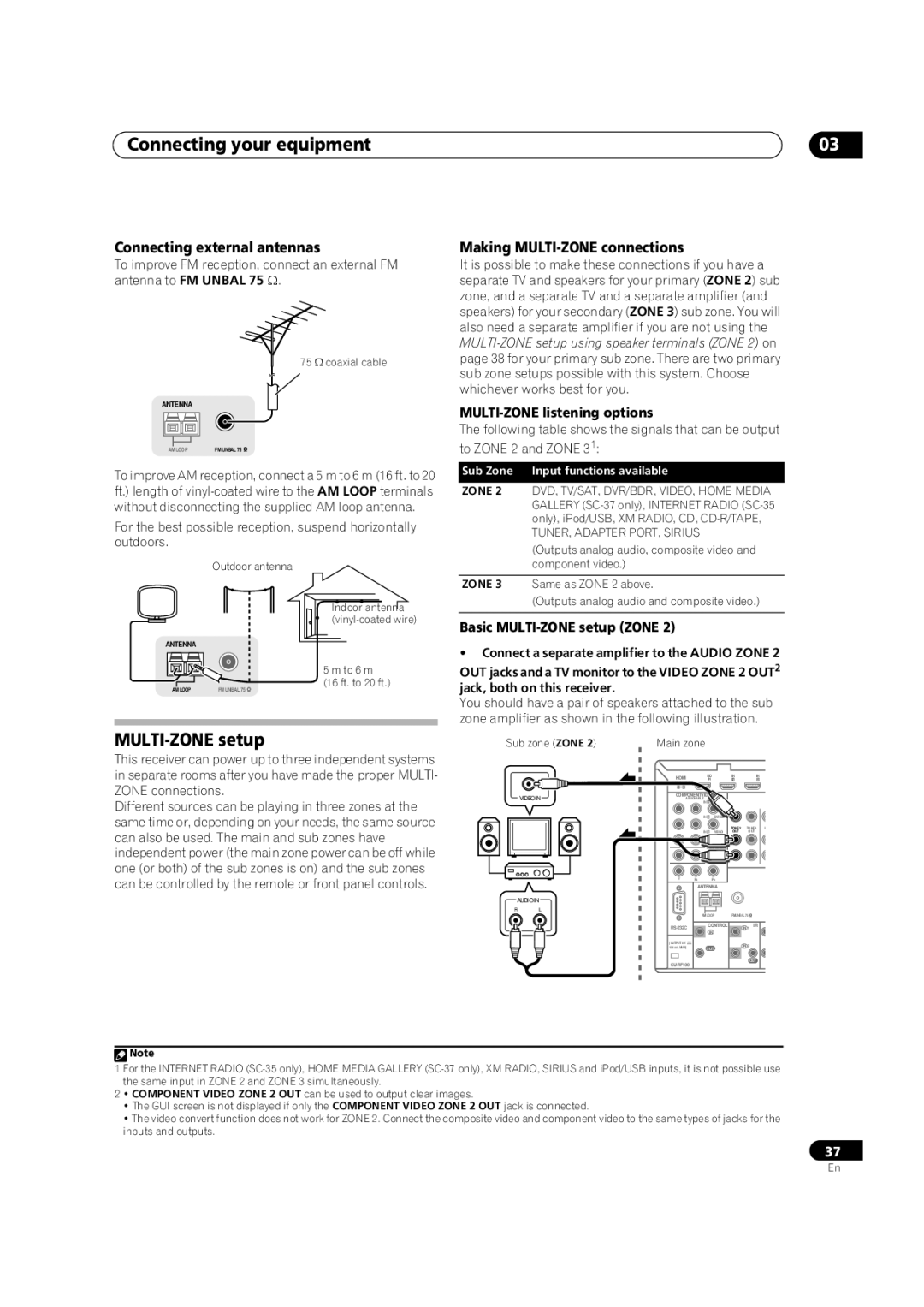
Connecting external antennas
MULTI-ZONE setup
Basic MULTI-ZONE setup Zone
Making MULTI-ZONE connections
MULTI-ZONE setup using speaker terminals Zone
Connecting to the network through LAN interface
Secondary MULTI-ZONE setup Zone
LAN terminal specifications
Connecting an XM Radio tuner
Connecting your equipment Connecting Optional Bluetooth
Connecting a SiriusConnect tuner
Connecting a USB device for Advanced Mcacc output
Connecting a USB device
Operating other Pioneer components with this unit’s sensor
Connecting your equipment Connecting an IR receiver
Decide which component you want to use the remote sensor
Unit, a piece of furniture, or other object on
Plugging in the receiver
Basic Setup Chapter
Basic Setup
Switch on the receiver and your TV
Changing the OSD display language OSD Language
Select the parameters you want to set.3
Basic Setup
Problems when using the Auto Mcacc Setup
Input Setup menu
Home Media
Input function default and possible settings
Internet
XM Radio
Basic playback Chapter
Basic playback
Playing a source
Playing a source with Hdmi connection
Playing back audio files stored on an iPod
Basic playback Playing an iPod
Finding what you want to play
Basic playback controls
Press iPod Ctrl to switch the iPod controls
Switching the iPod controls1
Basic playback
Playing a USB device
When you’re finished, press Return
Slideshow Setup
Playing back photo files stored on a USB memory device2
You will return to the USB Top menu
Music files
About playable file formats
Photo files
Basic playback Listening to the radio
Listening to XM Radio
Naming station presets
Listening to Satellite Radio
Selecting channels and browsing by genre
Saving channel presets
Using XM HD Surround
Using the XM Menu
Listening to channel presets
Sirius Menu provides additional Sirius Radio features.2
Using the Sirius Menu
Select the channel you want to memorize
See Selecting channels and browsing by genre above
Programming the Internet radio stations
Basic playback Listening to Internet radio stations
Programming with the GUI screen
Programming on the computer screen
Wireless music play
Bluetooth Adapter for Wireless Enjoyment of Music
Remote control operation
Select ‘Internet Radio Setting’
Enter
Select the ‘Passcode’ setting you want
Connected appears in the receiver display.2
Adapter
Listening to your system Chapter
Listening to your system
Auto playback
Listening in surround sound
Listening to your system
Using the Home THX modes
Pro Logic IIx Movie See above Pro Logic IIx Music See above
PRO LOGIC+THX Cinema
Using the Advanced surround effects
Using Front Stage Surround Advance
Listening in stereo
Choosing the input signal
Listening to your system Using Stream Direct
Selecting Mcacc presets
Better sound using Phase Control
Fullband PHASE.4
Phase Control indicator on the front panel lights
Playback with Home Media Gallery inputs SC-37 only
Features of Home Media Gallery
Playback with Home Media Gallery inputs SC-37 only Chapter
Introduction Enjoying the Home Media Gallery
Source
Playback with Home Media Gallery inputs SC-37 only
Repeat to play back the desired song
Sirius See Listening to Sirius Internet Radio on
Listening to Rhapsody
Listening to Internet radio stations
About list of Internet radio
Saving and retrieving Internet radio stations
Advanced operations for Internet radio
Checking about the Accounts
Content playable over a network
About network playback
Windows Media Player
About playback behavior over a network
Software update
AAC
Lpcm
Flac
Playback with Home Media Gallery inputs SC-37 only Glossary
Control with Hdmi function Chapter
Control with Hdmi function
Making Control with Hdmi connections
Before using synchronization
Control with Hdmi function Hdmi Setup
Control with Hdmi function About synchronized operations
Control with Hdmi function Setting the Pqls function
Using other functions Chapter
Using other functions
Setting the Audio options
Press Return to confirm and exit the menu
Using other functions
Progressive
Setting the Video options
Auto
Using the MULTI-ZONE controls
Switching the speaker terminals
MULTI-ZONE remote controls
Reducing the level of an analog signal
Making an audio or a video recording
Select the source you want to record
Switching the Hdmi output
Using other functions Using the sleep timer
Checking your system settings
Dimming the display
Default system settings
Using other functions Resetting the system
Display shows Reset no
Setting Default
Controlling the rest of your system In case of SC-37
About the Remote Setup menu
Selecting preset codes directly
Setting the remote to control other components
Use / to select the remote mode
Use / to select ‘PRESET RECALL’, then press
Erasing one of the remote control button settings
Programming signals from other remote controls
Controlling the rest of your system In case of SC-37
Menu
Resetting the remote control settings
Confirming preset codes
Renaming input function names manually
Direct function
Programming a multi-operation or a shutdown sequence
Multi Operation and System Off
Using System off
Using multi operations
Controlling components
Press Multi Operation
Enter
Buttons TV Monitor
Audio
Disp
Buttons
Audio Power OFF Disp Aspect
Buttons TV Projector
CONTRAST+
Receiver
Press the Setting button on the front of the RF adapter
Pairing the RF adapter and remote control
Operating this receiver by RF communications
Operating other components by RF communications
Manual flashes in the remote display.1
Use / to select ‘SYNC RENAMING’, then press
Use /to select ‘AUTO’ or ‘MANUAL’, then press
Press ENTER.2
Other devices using 2.4 GHz
Precautions regarding wavelength
Use / to select ‘OPERATION MODE’, then press
Examples of common devices utilizing the 2.4 GHz band
Usable range
Signal reflection
For safe use
Controlling the rest of your system In case of SC-35
Press and hold R.SETUP, then press 4 for three seconds
Controlling the rest of your system In case of SC-35
Press and hold R.SETUP, then press 1 for three seconds
Press R.SETUP to exit the preset setup mode
Use the number buttons to enter the 4-digit preset code
See Preset code list SC-35 only on
Erasing all learnt settings that are in one input function
Press Multi Operation and then Source to
Press and hold R.SETUP, then press 6 for three seconds
Programming a Multi operation or a shutdown sequence
Erasing the settings for the multi-operation
Press and hold R.SETUP, then press 0 for three seconds
Default preset codes
Input function button Preset code
LED flashes continuously
+/- a
HDD Red
CLEARb
Sacd SETUPa
OPEN/CLOSEb
/// ///
Advanced Mcacc menu
Making receiver settings from the Advanced Mcacc menu
Advanced Mcacc menu Chapter
Automatic Mcacc Expert
Select the parameters you want to set
Advanced Mcacc menu
Select ‘Manual MCACC’ from the Advanced Mcacc menu
Manual Mcacc setup
Fine Channel Level
Adjust the level of the left channel
Fine Speaker Distance
Standing Wave
How to use Acoustic Calibration EQ Professional
Acoustic Calibration EQ Adjust
Type B Reverb characteristics for different channels
Acoustic Calibration EQ Professional
Reverb characteristics are displayed when the Full
Using Acoustic Calibration EQ Professional
Precision Distance SC-37 only
Checking Mcacc Data
USB device to check it on the computer’s screen as well
Group Delay SC-37 only
Speaker Setting
Channel Level
Speaker Distance
You will return to the Data Management setup menu
Renaming Mcacc presets
Data Management
Output Mcacc data
Clearing Mcacc presets
Copying Mcacc preset data
System Setup and Other Setup menus Chapter
System Setup and Other Setup menus
Making receiver settings from System Setup menu
Manual speaker setup
Speaker system setting
System Setup and Other Setup menus
Select ‘Speaker System’ from the Manual SP Setup menu
Select the speaker system setting
Confirm your selected setup option
Select ‘Channel Level’ from the Manual SP Setup menu
Adjust the level of each channel using /
Test tones will start after you press Enter
THX Audio Setting
Network Setup menu
Curve
Manual
Checking the MAC address
IP address/Proxy setting
Network Standby
Remote Control Mode Setup
Volume Setup
Flicker Reduction Adjusts the way the GUI screen looks
Select the Mute Level setting you want
RF Remote Setup SC-37 only
Flicker Reduction Setup
Multi Channel Input Setup
Extension Setup SC-35 only
Additional information
Speaker Setting Guide
Additional information Chapter
Power
Troubleshooting
Additional information
Positional relationship between speakers and monitor
No sound
SymptomRemedy
Other audio problems
Symptom
Home Menu
Video
Settings
Display
Professional Calibration EQ graphical output
SEL
Digital or DTS does not
Symptoms Causes Remedies
Remote control
Web Control
Hdcp Error shows
Receiver to a component or TV with the DeepColor feature
Between source and receiver
For your component
Configuration B
Configuration a
Important information regarding the Hdmi connection
USB interface
XM radio messages
Internet radio SC-35 only
Status messages Cause
Action
Status messages Cause Check Antenna
Sirius radio messages
Tuner Home Dock or the XM antenna cable is
Damaged
Status messages Cause Action
Home Media Gallery SC-37 only
Status messages Descriptions
About status messages SC-37 only
Starting H.M.G
About THX
Surround sound formats
Windows Media Audio 9 Professional
Dolby
Timbre Matching
Re-Equalization
Adaptive Decorrelation
THX Ultra2/Select2 Plus
About Sirius and XM
About iPod
About Flac
Flac Decoder
Multichannel signal formats
Stereo 2 channel signal formats
Preset code
Additional information Preset code list SC-35 only
Example Category
Manufacturer
DVD
Satellite Set Top Box
VCR
Cable Set Top Box
Satellite Set Top Box SAT/PVR Combination
Cable Set Top Box Cable/PVR Combination
Laser Disc Player
Additional information Specifications
Mcacc Setup microphone APM7009 Omni-directional
Cleaning the unit
Number of Furnished Parts
Incase of SC-37
To establish a safe level
We Want You Listening For a Lifetime
Once you have established a comfortable sound level
Decibel Level Example
146
147
USA/Aux Etats-Unis Canada/Aux Canada