Chapter 3
Operation
This chapter provides the following information for the
•
•Operating procedures
Installation procedures given in Chapter 2 must be completed and checked before attempting to operate
3.1 Controls and Indicators
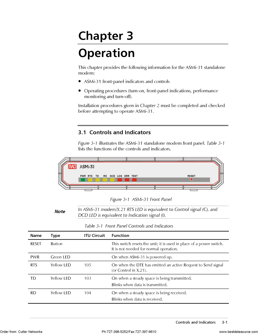
Figure 3-1 illustrates the ASMi-31 standalone modem front panel. Table 3-1 lists the functions of the controls and indicators.
PWR RTS TD RD DCD LOS ERR TEST | RESET | ||||||||||||||||
|
|
|
|
|
|
|
|
|
|
|
|
|
|
|
|
|
|
|
|
| Figure |
|
|
| |
| Note | In | |
| DCD LED is equivalent to Indication signal (I). | ||
|
| ||
|
| Table | Front Panel Controls and Indicators |
|
|
|
|
Name | Type | ITU Circuit | Function |
|
|
|
|
RESET | Button |
| This switch resets the unit; it is used in place of a power switch. |
|
|
| It is not needed for normal operation. |
|
|
|
|
PWR | Green LED |
| On when |
|
|
|
|
RTS | Yellow LED | 105 | On when the DTE has emitted an active Request to Send signal |
|
|
| (or Control in X.21). |
|
|
|
|
TD | Yellow LED | 103 | On when a steady space is being transmitted. |
|
|
| Blinks when data is transmitted. |
|
|
|
|
RD | Yellow LED | 104 | On when a steady space is being received. |
|
|
| Blinks when data is received. |
|
|
|
|
Controls and Indicators
Order from: Cutter Networks | www.bestdatasource.com |