Appendix B. | |
|
|
LINE FUSE | G.703 |
| |
| 230 V/0.1A T 250V GND XMT RCV |
![]() LINE
LINE![]()
![]()
![]() GND
GND
2 4 5
RCV (3, 6)
GND (2) | XMT (4, 5) |
|
1 8
(9,11) RCV | 2 | |
(2,16) XMT | ||
| ||
(7) GND | 7 | |
| ||
| 9 | |
16 | 11 | |
|
Terminal Block |
|
|
(Standalone) | (Standalone) | (Rack Version) |
Note
Note
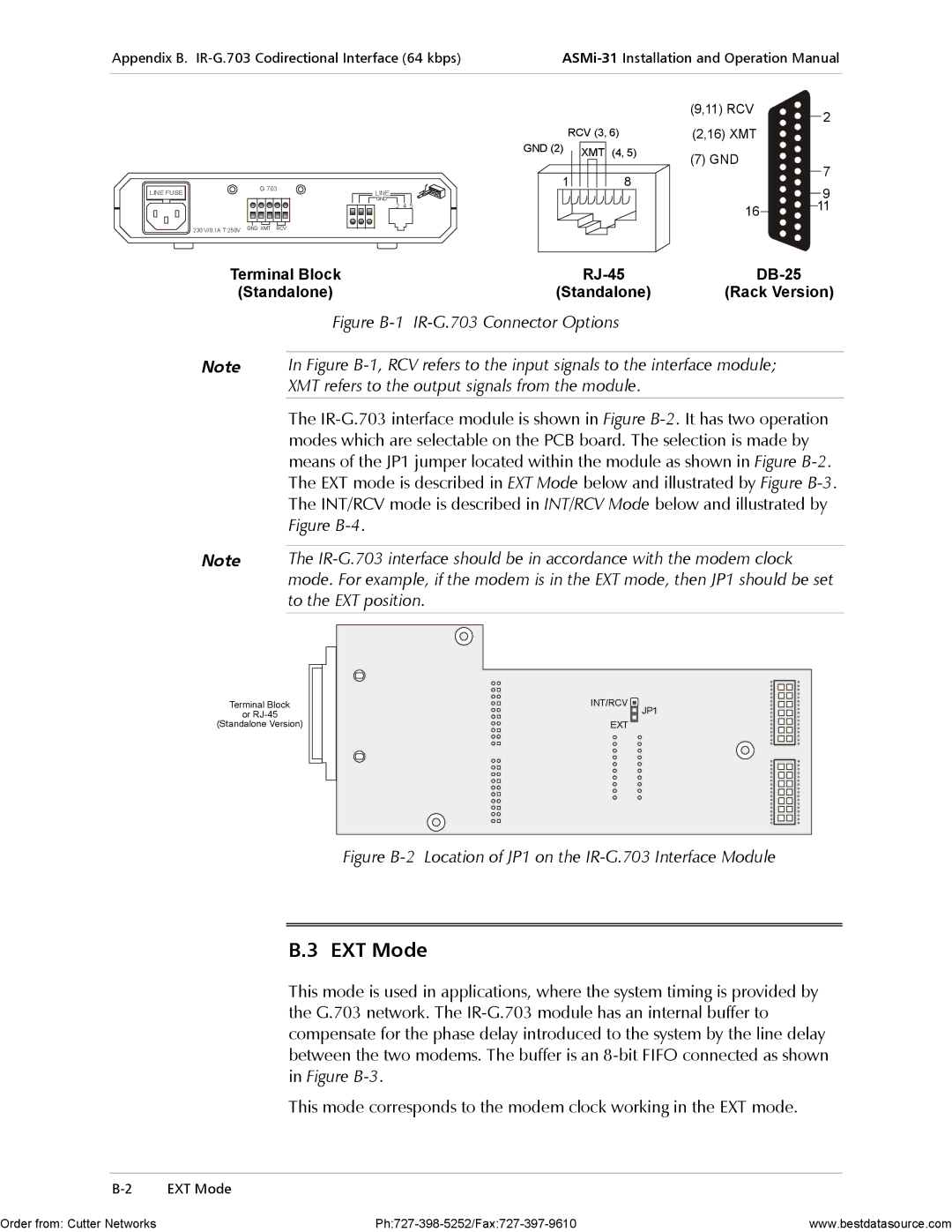
Figure B-1 IR-G.703 Connector Options
In Figure B-1, RCV refers to the input signals to the interface module; XMT refers to the output signals from the module.
The
The
Terminal Block
or
(Standalone Version)
INT/RCV |
JP1 |
EXT |
Figure B-2 Location of JP1 on the IR-G.703 Interface Module
B.3 EXT Mode
This mode is used in applications, where the system timing is provided by the G.703 network. The
This mode corresponds to the modem clock working in the EXT mode.
Order from: Cutter Networks | www.bestdatasource.com |