Appendix D. DTE Interface ConnectorsASMi-31Installation and Operation Manual
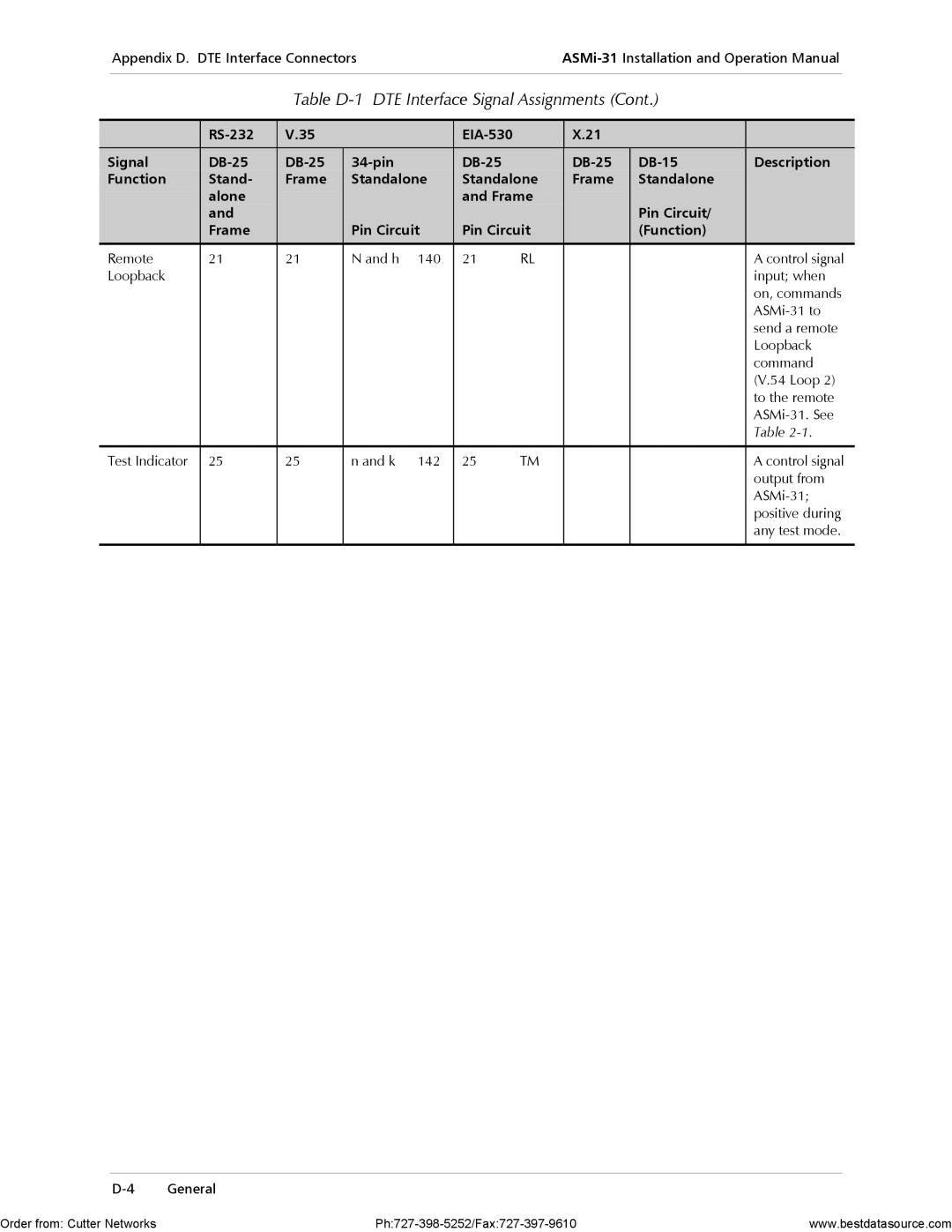
Table D-1 DTE Interface Signal Assignments (Cont.)
| V.35 |
|
|
| X.21 |
|
| ||
|
|
|
|
|
|
|
|
|
|
Signal |
|
| Description | ||||||
Function | Stand- | Frame | Standalone | Standalone | Frame | Standalone |
| ||
| alone |
|
|
| and Frame |
|
|
| |
| and |
|
|
|
|
|
| Pin Circuit/ |
|
| Frame |
| Pin Circuit | Pin Circuit |
| (Function) |
| ||
|
|
|
|
|
|
|
|
|
|
Remote | 21 | 21 | N and h | 140 | 21 | RL |
|
| A control signal |
Loopback |
|
|
|
|
|
|
|
| input; when |
|
|
|
|
|
|
|
|
| on, commands |
|
|
|
|
|
|
|
|
| |
|
|
|
|
|
|
|
|
| send a remote |
|
|
|
|
|
|
|
|
| Loopback |
|
|
|
|
|
|
|
|
| command |
|
|
|
|
|
|
|
|
| (V.54 Loop 2) |
|
|
|
|
|
|
|
|
| to the remote |
|
|
|
|
|
|
|
|
| |
|
|
|
|
|
|
|
|
| Table |
|
|
|
|
|
|
|
|
|
|
Test Indicator | 25 | 25 | n and k | 142 | 25 | TM |
|
| A control signal |
|
|
|
|
|
|
|
|
| output from |
|
|
|
|
|
|
|
|
| |
|
|
|
|
|
|
|
|
| positive during |
|
|
|
|
|
|
|
|
| any test mode. |
|
|
|
|
|
|
|
|
|
|
Order from: Cutter Networks | www.bestdatasource.com |