Appendix A. Ethernet Interface | ||
|
|
|
|
|
|
|
|
|
A.5 Installation and Operation
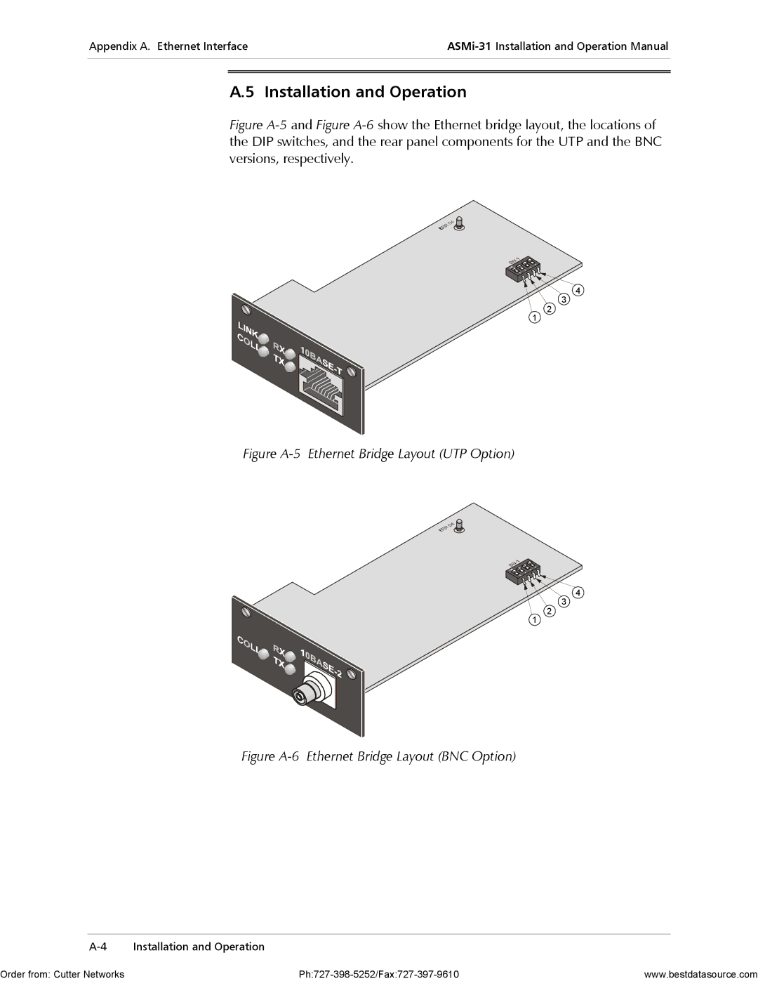
Figure A-5 and Figure A-6 show the Ethernet bridge layout, the locations of the DIP switches, and the rear panel components for the UTP and the BNC versions, respectively.
4
3
2
1
Figure A-5 Ethernet Bridge Layout (UTP Option)
4
3
2
1
Figure A-6 Ethernet Bridge Layout (BNC Option)
Order from: Cutter Networks | www.bestdatasource.com |