Chapter 5 - Operating instructions
It is also possible to operate the camera without a Triax cable by supplying a +12 Vdc supply to the DC input socket. The BATT indicator in the viewfinder lights if the camera supply voltage is less than 11V when using an external supply.
If excessive current flows in the camera or adapter, the circuit breaker trips and shuts off power to all the units. If this happens check the units for faults and if necessary take corrective action before pressing the circuit breaker button to reset the power.
5.8.2 Selecting monitoring signals
Viewfinder display signal
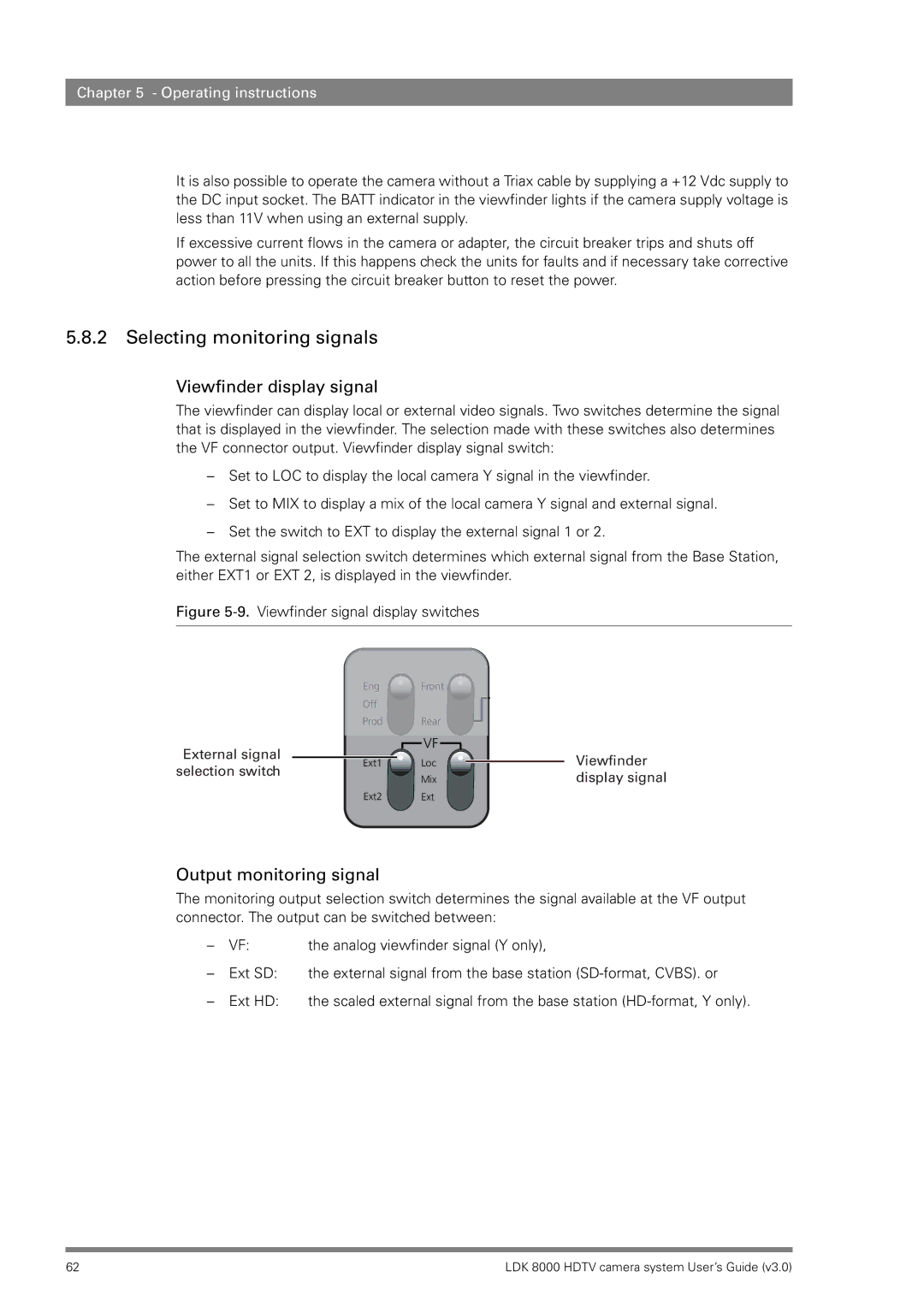
The viewfinder can display local or external video signals. Two switches determine the signal that is displayed in the viewfinder. The selection made with these switches also determines the VF connector output. Viewfinder display signal switch:
–Set to LOC to display the local camera Y signal in the viewfinder.
–Set to MIX to display a mix of the local camera Y signal and external signal.
–Set the switch to EXT to display the external signal 1 or 2.
The external signal selection switch determines which external signal from the Base Station, either EXT1 or EXT 2, is displayed in the viewfinder.
Figure 5-9. Viewfinder signal display switches
External signal selection switch
Eng ![]() Front
Front ![]()
Off
Prod Rear
|
|
|
|
| VF |
|
|
|
| Viewfinder |
|
| Loc |
|
|
|
| ||||
Ext1 |
|
|
|
|
|
| ||||
|
|
|
|
| ||||||
|
|
|
| Mix |
|
|
|
| display signal | |
Ext2 |
| Ext |
|
|
|
|
| |||
Output monitoring signal
The monitoring output selection switch determines the signal available at the VF output connector. The output can be switched between:
– | VF: | the analog viewfinder signal (Y only), |
– | Ext SD: | the external signal from the base station |
– | Ext HD: | the scaled external signal from the base station |
62 | LDK 8000 HDTV camera system User’s Guide (v3.0) |