Chapter 7 - Connectors
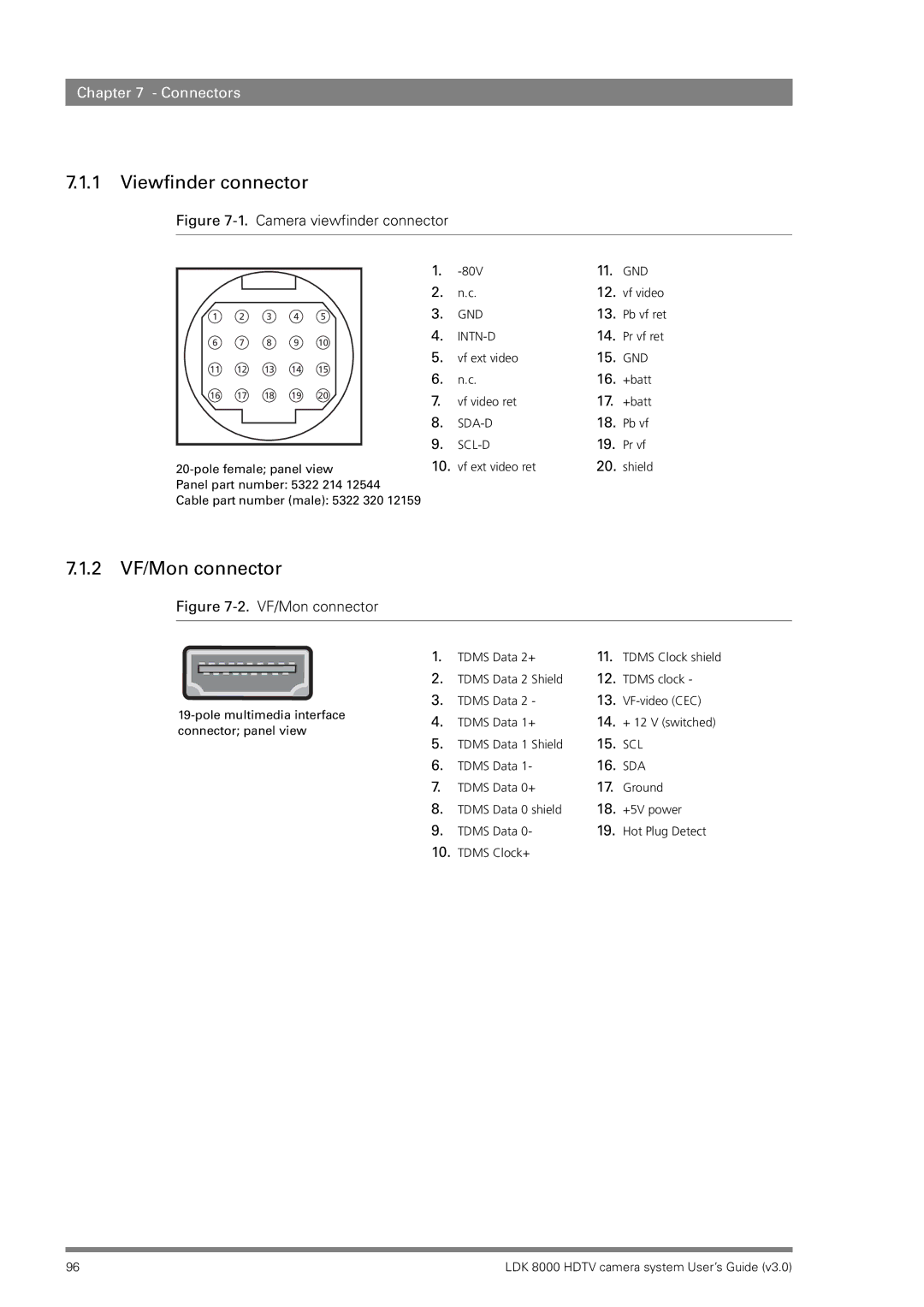
7.1.1 Viewfinder connector
Figure 7-1. Camera viewfinder connector
|
|
|
|
|
| 1. | 11. | GND | |
|
|
|
|
|
| ||||
|
|
|
|
|
| 2. | n.c. | 12. | vf video |
1 | 2 | 3 | 4 | 5 |
| 3. | GND | 13. | Pb vf ret |
6 | 7 | 8 | 9 | 10 |
| 4. | 14. | Pr vf ret | |
|
|
|
|
| |||||
11 | 12 | 13 | 14 | 15 |
| 5. | vf ext video | 15. | GND |
| 6. | n.c. | 16. | +batt | |||||
|
|
|
|
|
| ||||
16 | 17 | 18 | 19 | 20 |
| 7. | vf video ret | 17. | +batt |
|
|
|
|
|
| ||||
|
|
|
|
|
| 8. | 18. | Pb vf | |
|
|
|
|
|
| 9. |
| 19. | Pr vf |
|
|
|
|
|
| ||||
10. | vf ext video ret | 20. | shield | ||||||
Panel part number: 5322 214 12544 |
|
|
|
| |||||
Cable part number (male): 5322 320 12159 |
|
|
|
| |||||
7.1.2 VF/Mon connector
Figure 7-2. VF/Mon connector
| 1. | TDMS Data 2+ | 11. | TDMS Clock shield | ||
| 2. | TDMS Data 2 | Shield | 12. | TDMS clock - | |
3. | TDMS Data 2 | - | 13. | |||
4. | TDMS Data 1+ | 14. | + 12 V (switched) | |||
connector; panel view | ||||||
5. | TDMS Data 1 | Shield | 15. | SCL | ||
| ||||||
| 6. | TDMS Data 1- | 16. | SDA | ||
| 7. | TDMS Data 0+ | 17. | Ground | ||
| 8. | TDMS Data 0 shield | 18. | +5V power | ||
| 9. | TDMS Data 0- | 19. | Hot Plug Detect | ||
| 10. | TDMS Clock+ |
|
|
| |
96 | LDK 8000 HDTV camera system User’s Guide (v3.0) |
