|
|
|
|
| Unit 3: Installation | |
|
|
|
|
|
|
|
|
|
|
|
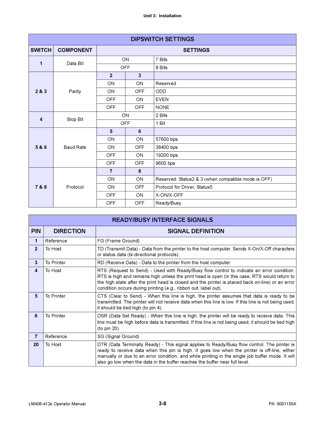
| DIPSWITCH SETTINGS | |
|
|
|
|
|
|
|
SWITCH | COMPONENT |
|
|
| SETTINGS | |
|
|
|
|
|
|
|
1 |
| Data Bit | ON |
| 7 Bits | |
|
|
|
|
| ||
| OFF |
| 8 Bits | |||
|
|
|
| |||
|
|
| 2 |
| 3 |
|
|
|
| ON |
| ON | Reserved |
2 & 3 | Parity |
|
|
|
| |
ON |
| OFF | ODD | |||
|
|
|
|
|
|
|
|
|
| OFF |
| ON | EVEN |
|
|
|
|
|
|
|
|
|
| OFF |
| OFF | NONE |
4 |
| Stop Bit | ON |
| 2 Bits | |
|
|
|
|
| ||
| OFF |
| 1 Bit | |||
|
|
|
| |||
|
|
| 5 |
| 6 |
|
|
|
| ON |
| ON | 57600 bps |
5 & 6 | Baud Rate |
|
|
|
| |
ON |
| OFF | 38400 bps | |||
|
|
|
|
|
|
|
|
|
| OFF |
| ON | 19200 bps |
|
|
|
|
|
|
|
|
|
| OFF |
| OFF | 9600 bps |
|
|
| 7 |
| 8 |
|
|
|
| ON |
| ON | Reserved: Status2 & 3 (when compatible mode is OFF) |
7 & 8 | Protocol |
|
|
|
| |
ON |
| OFF | Protocol for Driver, Status5 | |||
|
|
|
|
|
|
|
|
|
| OFF |
| ON |
|
|
|
|
|
|
|
|
|
|
| OFF |
| OFF | Ready/Busy |
|
|
|
|
|
|
|
|
|
| READY/BUSY INTERFACE SIGNALS | |||
|
|
|
|
|
|
|
PIN |
| DIRECTION |
|
|
| SIGNAL DEFINITION |
|
|
|
|
|
| |
1 | Reference | FG (Frame Ground) |
| |||
2 | To Host | TD (Transmit Data) - Data from the printer to the host computer. Sends | ||||
|
|
| or status data | |||
3 | To Printer | RD (Receive Data) - Data to the printer from the host computer. | ||||
4 | To Host | RTS (Request to Send) - Used with Ready/Busy flow control to indicate an error condition. | ||||
|
|
| RTS is high and remains high unless the print head is open (in this case, RTS would return to | |||
|
|
| the high state after the print head is closed and the printer is placed back | |||
|
|
| condition occurs during printing (e.g., ribbon out, label out). | |||
5 | To Printer | CTS (Clear to Send) - When this line is high, the printer assumes that data is ready to be | ||||
|
|
| transmitted. The printer will not receive data when this line is low. If this line is not being used, | |||
|
|
| it should be tied high (to pin 4). | |||
6 | To Printer | DSR (Data Set Ready) - When this line is high, the printer will be ready to receive data. This | ||||
|
|
| line must be high before data is transmitted. If this line is not being used, it should be tied high | |||
|
|
| (to pin 20). |
|
| |
7 | Reference | SG (Signal Ground) |
| |||
20 | To Host | DTR (Data Terminally Ready) - This signal applies to Ready/Busy flow control. The printer is | ||||
|
|
| ready to receive data when this pin is high. It goes low when the printer is | |||
|
|
| manually or due to an error condition, and while printing in the single job buffer mode. It will | |||
|
|
| also go low when the data in the buffer reaches the buffer near full level. | |||
PN: 9001155A |