SECTION 6: FLUE INSTALLATION
5.Refit the air intake spigot to the flexible hose re- using the hose clamp and to the upper panel using the original screws.
6.Align the flues’ inner and outer spigots and attach through the holes in the upper panel re- using the original screws.
7.Refit the lower door.
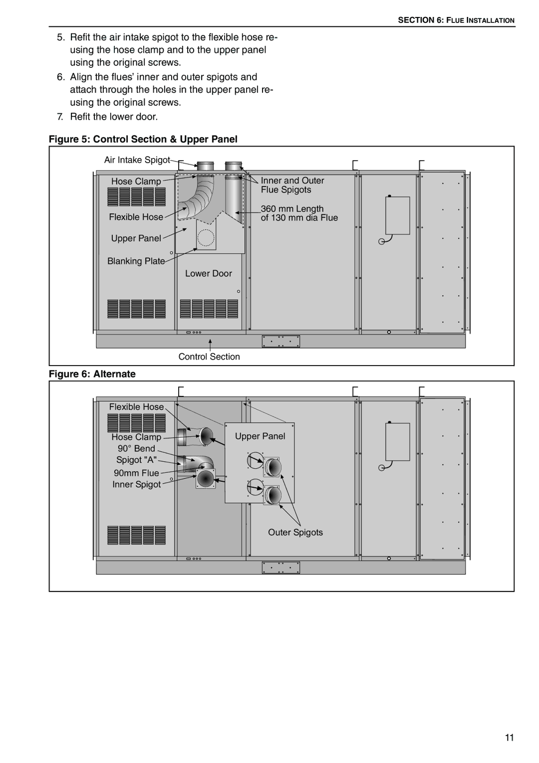
Figure 5: Control Section & Upper Panel
Air Intake Spigot
Hose Clamp | Inner and Outer |
| Flue Spigots |
Flexible Hose | 360 mm Length |
of 130 mm dia Flue | |
Upper Panel |
|
Blanking Plate |
|
| Lower Door |
Control Section
Figure 6: Alternate
Flexible Hose |
|
Hose Clamp | Upper Panel |
90° Bend |
|
Spigot "A" |
|
90mm Flue |
|
Inner Spigot |
|
| Outer Spigots |
11