DUALAIR® HEATING AND COOLING UNITS INSTALLATION OPERATION AND SERVICE MANUAL
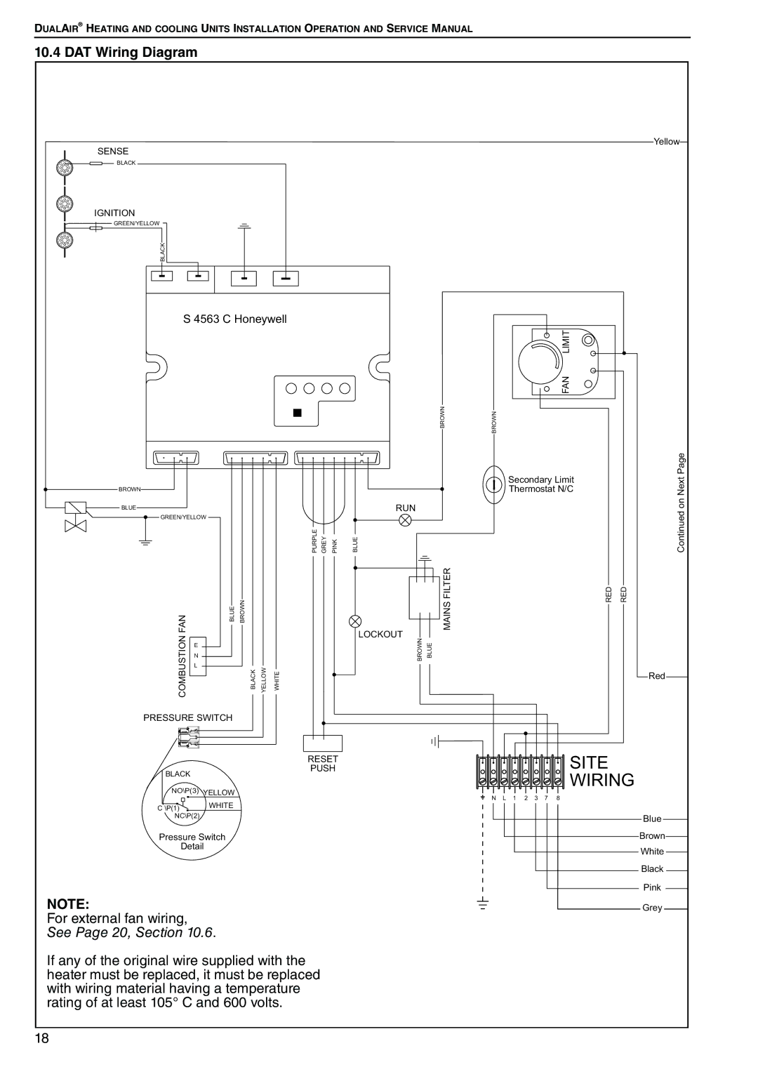
10.4 DAT Wiring Diagram
SENSE |
|
|
|
|
|
|
|
|
| Yellow |
|
|
|
|
|
|
|
|
|
| |
BLACK |
|
|
|
|
|
|
|
|
|
|
IGNITION |
|
|
|
|
|
|
|
|
|
|
GREEN/YELLOW |
|
|
|
|
|
|
|
|
|
|
BLACK |
|
|
|
|
|
|
|
|
|
|
S 4563 C Honeywell |
|
|
|
|
|
| ||||
|
|
|
|
|
|
|
|
| LIMIT |
|
|
|
|
|
|
|
|
|
| FAN |
|
|
|
|
|
|
|
|
| BROWN | BROWN |
|
|
|
|
|
|
|
|
|
| Secondary Limit | Page |
|
|
|
|
|
|
|
|
| Nexton | |
BROWN |
|
|
|
|
|
|
|
| Thermostat N/C | |
BLUE |
|
|
| PURPLE GREY | PINK | BLUE | RUN |
|
| Continued |
GREEN/YELLOW |
|
|
|
|
| |||||
|
|
|
|
|
|
|
|
| ||
FAN |
| BLUE BROWN |
|
|
|
| LOCKOUT | MAINS FILTER | RED | RED |
COMBUSTION |
| BLACK | YELLOW | WHITE |
|
| BROWN BLUE |
|
| |
E |
|
|
|
|
| |||||
|
|
|
|
|
|
|
|
|
| |
| N |
|
|
|
|
|
|
|
|
|
| L |
|
|
|
|
|
|
|
|
|
|
|
|
|
|
|
|
|
|
| Red |
PRESSURE SWITCH |
|
|
|
|
|
|
|
| ||
|
| PUSH | SITE |
|
| RESET | WIRING |
BLACK |
|
| |
NO\P(3) YELLOW | N L 1 | 2 3 7 8 | |
| WHITE | ||
C \P(1) |
|
| |
|
|
| |
NC\P(2) |
|
| Blue |
Pressure Switch |
| Brown | |
Detail |
|
| White |
|
|
| |
|
|
| Black |
|
|
| Pink |
NOTE: |
|
| Grey |
For external fan wiring, |
|
|
|
See Page 20, Section 10.6.
If any of the original wire supplied with the heater must be replaced, it must be replaced with wiring material having a temperature rating of at least 105° C and 600 volts.
18