SECTION 10: WIRING AND ELECTRICAL INFORMATION
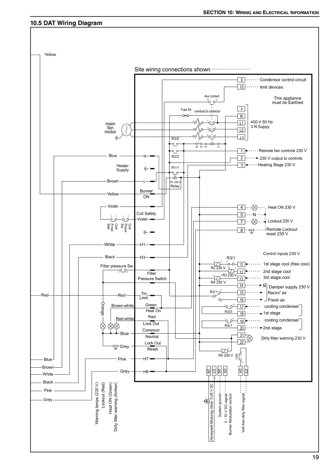
10.5 DAT Wiring Diagram
Yellow |
|
|
|
|
|
|
|
|
|
|
|
|
|
|
|
|
|
|
|
|
|
|
|
|
|
| Site wiring connections shown |
|
|
|
|
|
|
|
| ||||
|
|
|
|
|
|
|
|
|
|
|
|
|
|
|
|
|
| 9 | Condensor control circuit |
|
|
|
|
|
|
|
|
|
|
|
|
|
|
|
|
|
| 10 | limit devices |
|
|
|
|
|
|
|
|
|
|
| Aux contact |
|
|
|
| This appliance | |||
|
|
|
|
|
|
|
|
|
|
| 14 |
| 13 |
|
|
|
| ||
|
|
|
|
|
|
|
|
|
|
|
|
|
|
|
|
|
|
| must be Earthed |
|
|
|
|
|
|
|
| Fuse 5A | overload & contactor |
|
|
|
|
| |||||
|
|
|
|
|
|
|
|
|
|
|
|
|
|
|
|
|
| N |
|
|
| main |
|
|
| 2 |
|
| 2 |
| 1 |
|
|
|
| L1 | 400 V 50 Hz | ||
|
|
| fan |
|
|
| 4 |
|
| 4 |
| 3 |
|
|
|
| L2 | 3 N Suppy | |
|
| motor |
|
|
|
|
|
|
|
|
|
|
|
|
|
| |||
|
|
|
|
| 6 |
|
| 6 |
| 5 |
|
|
|
|
|
| |||
|
|
|
|
|
|
|
|
|
|
|
|
|
|
| L3 |
| |||
|
|
|
|
|
|
|
| R3/2 |
|
|
|
|
|
|
|
|
|
| |
|
|
|
|
|
|
|
|
| 96 | 95 | A2 |
|
| A1 |
|
|
|
| Remote fan controls 230 V |
|
|
| Blue |
|
|
|
|
|
|
|
|
|
|
|
|
| 1 | ||
|
|
|
|
| N | R2/2 |
|
|
|
|
|
|
|
|
| 2 | 230 V output to controls | ||
|
|
|
|
|
|
|
|
|
|
|
|
|
|
|
|
|
| ||
|
|
|
| Heater |
| R1/1 |
|
|
|
|
|
|
|
|
| 3 | Heating Stage 230 V | ||
|
|
|
| Supply |
|
|
|
|
|
|
|
|
|
|
|
| |||
|
|
|
|
|
|
|
|
|
|
|
|
|
|
|
|
| |||
|
|
| Brown |
|
| L | R1 230 V |
|
|
|
|
|
|
|
|
|
|
| |
|
|
|
|
|
|
|
| Relay |
|
|
|
|
|
|
|
|
|
|
|
|
|
| Yellow |
|
| Burner |
|
|
|
|
|
|
|
|
|
|
|
| |
|
|
|
|
| ON |
|
|
|
|
|
|
|
|
|
|
|
| ||
|
|
|
|
|
|
|
|
|
|
|
|
|
|
|
|
|
|
| |
|
|
| Violet |
|
|
|
|
|
|
|
|
|
|
|
|
| 4 | Heat ON 230 V | |
|
|
| 3 | 1 | 3 | 2 | Coil Safety |
|
|
|
|
|
|
|
|
|
| 5 | N |
|
|
|
|
|
|
| Violet |
|
|
|
|
|
|
|
|
|
| 7 | Lockout 230 V |
|
|
| Coil Frost Stat | Coil Press Sw |
|
|
|
|
|
|
|
|
|
|
| ||||
|
|
|
|
|
|
|
|
|
|
|
|
|
| 8 | Remote Lockout | ||||
|
|
|
|
|
|
|
|
|
|
|
|
|
|
|
|
|
|
| reset 230 V |
| White |
|
| H1 |
|
|
|
|
|
|
|
|
|
|
|
| |||
|
|
|
|
|
|
| 1 |
|
|
|
|
|
|
|
|
|
|
|
|
|
| Black |
|
| H3 |
|
|
|
|
|
|
| R3/1 |
|
| Control inputs 230 V | |||
|
|
|
|
|
|
|
|
|
| 2 |
|
|
| ||||||
|
|
|
|
|
|
|
|
|
|
|
| 7 |
| 4 | 1 |
| 11 | 1st stage cool (free cool) | |
| Filter pressure Sw |
|
|
|
| R2 230 V | 10 | 2 | |||||||||||
|
|
|
|
|
|
| Filter |
|
|
| 12 | 2nd stage cool | |||||||
|
|
|
| 3 |
| 2 |
|
|
|
|
|
| 2 R3 230 V | ||||||
|
|
|
|
|
|
| Pressure Switch |
|
|
|
| 7 |
| 13 | 3rd stage cool | ||||
|
|
|
|
|
|
|
|
|
|
|
|
|
|
|
|
| |||
|
|
|
|
|
|
|
|
|
| R4 230 V |
|
|
| ||||||
|
|
|
|
|
|
|
|
|
|
|
|
| 14 | N Damper supply 230 V | |||||
|
|
|
|
|
|
|
|
|
|
|
|
|
| 4 |
|
|
| ||
Red |
|
|
| Red |
| TH |
|
|
| R2/1 |
|
|
| 15 | Recirc' air | ||||
|
|
|
|
|
|
|
|
|
|
|
|
|
| ||||||
|
|
|
|
|
|
| Limit |
|
|
|
| 1 |
|
|
|
|
| 16 | Fresh air |
|
|
|
|
|
|
|
|
|
|
|
|
|
|
|
|
| |||
| Orange |
|
|
|
| Green |
|
|
|
|
|
| 3 |
|
|
| |||
|
|
|
|
|
|
|
| 9 | 11 |
| 18 | 1st stage | |||||||
|
|
|
|
|
|
|
|
|
|
| 17 | cooling condenser | |||||||
|
|
|
|
|
|
| Heat On |
|
|
|
|
|
|
| R3/3 |
|
|
| |
|
|
|
| Red |
|
|
|
|
|
|
| 1 | 3 |
| 19 | cooling condenser | |||
|
|
|
|
|
|
|
|
|
|
|
|
| |||||||
|
|
|
|
|
|
| Lock Out |
|
|
|
|
|
|
|
|
|
| ||
|
|
|
|
|
|
|
|
|
|
|
|
|
| R4/1 |
|
| |||
|
|
|
|
|
|
|
|
|
|
|
|
|
|
| 20 | 2nd stage | |||
|
|
|
|
|
|
| Common |
|
|
|
|
|
|
|
| ||||
|
|
|
|
|
|
|
|
|
|
|
|
|
|
|
|
| |||
|
|
|
|
| Blue |
|
|
|
|
|
|
|
|
|
| 21 |
| ||
|
|
|
|
| Neutral |
|
|
|
|
|
|
|
|
|
| Dirty filter warning 230 V | |||
|
|
|
|
|
|
|
|
|
|
|
|
|
|
|
|
| |||
|
|
|
|
|
|
| Lock Out |
|
|
|
|
|
|
|
|
|
| 22 | |
|
|
|
|
| Grey |
|
|
|
|
|
|
|
|
|
|
| |||
|
|
|
|
| Reset |
|
|
|
|
|
| 7 |
| 2 |
|
|
| ||
|
|
|
|
|
|
|
|
|
|
|
|
|
|
|
|
| |||
|
|
|
|
|
|
|
|
|
|
|
|
|
|
|
|
|
| 1 |
|
Blue |
|
|
| Pink |
| H7 |
|
|
|
|
|
| R5 230 V | R5/1 |
|
| |||
|
|
|
|
|
|
|
|
|
|
|
|
|
|
| |||||
|
|
|
|
|
|
|
|
|
|
|
|
|
| 3 |
| ||||
|
|
|
|
|
|
|
|
|
|
|
|
|
|
|
|
|
|
| |
Brown |
|
|
|
| Grey | H8 |
|
|
| 28 | 27 | 26 | 25 |
|
| 24 | 23 | ||
White |
|
|
|
|
|
|
|
|
| ||||||||||
|
|
|
|
|
|
|
|
|
|
|
|
|
|
|
|
|
|
| |
|
|
|
|
|
|
|
|
|
|
|
| + |
|
|
|
|
|
| |
Black | Lockout(Red) |
| HeatON (Green) | warningfilterDirty(Amber) |
|
|
|
|
|
|
| Systemground | ModulationBurnercontrol |
| filterdirtyfreeVoltsignal |
| |||
lampsWarning(230 V) |
|
|
|
|
|
|
|
|
|
| |||||||||
Pink |
|
|
|
|
|
|
|
|
|
|
|
|
|
|
|
|
|
|
|
Grey |
|
|
|
|
|
|
|
|
|
|
|
|
|
|
|
|
|
|
|
19