DUALAIR® HEATING AND COOLING UNITS INSTALLATION OPERATION AND SERVICE MANUAL
SECTION 8: OPTIONAL HEATER CONFIGURATIONS 8.1 Distribution Duct
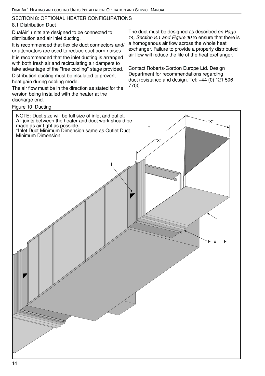
DualAir® units are designed to be connected to | The duct must be designed as described on Page | |
distribution and air inlet ducting. | 14, Section 8.1 and Figure 10 to ensure that there is | |
It is recommended that flexible duct connectors and/ | a homogenous air flow across the whole heat | |
or attenuators are used to reduce duct born noises. | exchanger. Failure to provide a properly distributed | |
air flow will reduce the life of the heat exchanger. | ||
It is recommended that the inlet ducting is arranged | ||
| ||
with both fresh air and recirculating air dampers to | Contact | |
take advantage of the "free cooling" stage provided. |
Distribution ducting must be insulated to prevent | Department for recommendations regarding | ||||||
duct resistance and design. Tel: +44 (0) 121 506 | |||||||
heat gain during cooling mode. | |||||||
7700 |
|
|
|
| |||
The air flow must be in the direction as stated for the |
|
|
|
| |||
|
|
|
|
|
| ||
version being installed with the heater at the |
|
|
|
|
|
| |
discharge end. |
|
|
|
|
|
| |
Figure 10: Ducting |
|
|
|
|
|
| |
NOTE: Duct size will be full size of inlet and outlet. |
|
|
| Dimension | |||
|
|
| |||||
All joints between the heater and duct work should be |
| “X” | |||||
made as air tight as possible. |
|
|
|
|
|
| |
|
| *Minimum- |
|
| |||
*Inlet Duct Minimum Dimension same as Outlet Duct |
|
| |||||
Twice |
|
| |||||
Minimum Dimension |
|
| Dimension |
|
| ||
|
|
| |||||
|
|
| “X” | ||||
Airflow Indicator |
|
|
|
|
|
| |
|
|
|
|
|
| ||
|
|
|
|
|
| ||
|
|
|
|
|
| ||
|
|
|
|
|
| ||
![]() Ducting
Ducting
![]() Flexible Flange
Flexible Flange
14
