SECTION 15: TROUBLESHOOTING
15.3 Troubleshooting for Flame Supervision System
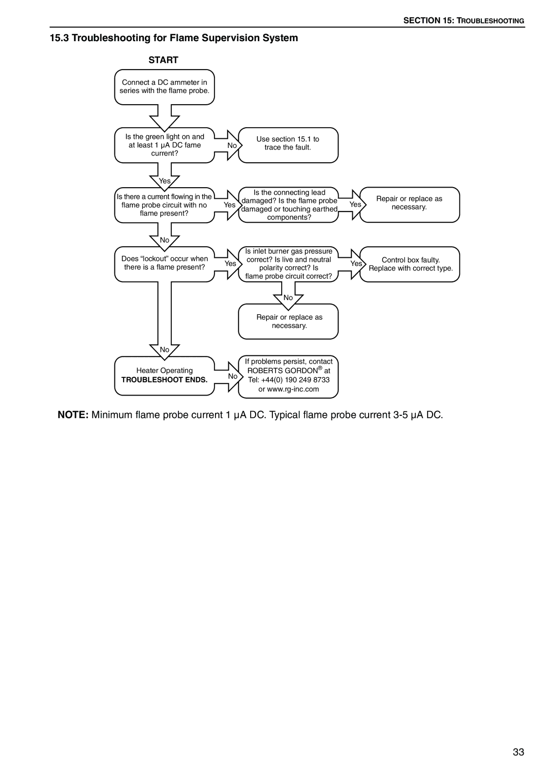
START
Connect a DC ammeter in series with the flame probe.
Is the green light on and at least 1 µA DC fame current?
Yes
Is there a current flowing in the
flame probe circuit with no
flame present?
No
Does “lockout” occur when there is a flame present?
No
Heater Operating
TROUBLESHOOT ENDS.
No | Use section 15.1 to |
|
|
trace the fault. |
|
| |
| Is the connecting lead |
| Repair or replace as |
Yes | damaged? Is the flame probe | Yes | |
damaged or touching earthed | necessary. | ||
| components? |
|
|
| Is inlet burner gas pressure |
|
|
Yes | correct? Is live and neutral | Yes | Control box faulty. |
polarity correct? Is | Replace with correct type. | ||
| flame probe circuit correct? |
|
|
| No |
|
|
| Repair or replace as |
|
|
| necessary. |
|
|
If problems persist, contact
No | ROBERTS GORDON® at | |
Tel: +44(0) 190 249 8733 | ||
| ||
| or |
NOTE: Minimum flame probe current 1 μA DC. Typical flame probe current
33