OfficeServ 7100 Installation Manual
3.2 Mounting Control Boards
This section describes how to set the switches of MP10/11 control board, mount the option boards, insert to the slots and connect MP10/11 board.
3.2.1 Setting Switches and Mounting Option Boards.
MP10/11 has the switches to set the board operation for the user’s purpose and fitting with the system configuration. The way to set the switches and mount the boards are as follows:
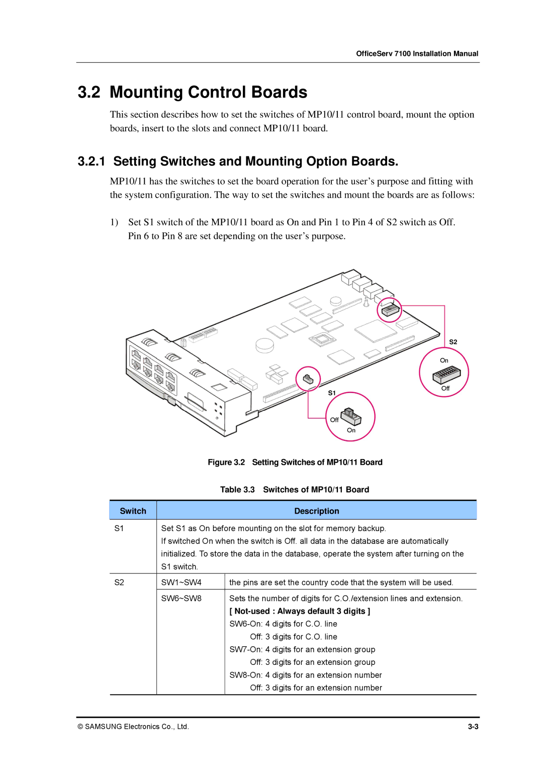
1)Set S1 switch of the MP10/11 board as On and Pin 1 to Pin 4 of S2 switch as Off. Pin 6 to Pin 8 are set depending on the user’s purpose.
S2
On
|
|
|
| S1 | Off |
|
|
|
|
| |
|
|
|
| Off |
|
|
|
|
| On |
|
|
|
| Figure 3.2 Setting Switches of MP10/11 Board |
| |
|
|
| Table 3.3 Switches of MP10/11 Board |
| |
|
|
|
|
|
|
| Switch |
|
| Description |
|
| S1 | Set S1 as On before mounting on the slot for memory backup. |
| ||
|
| If switched On when the switch is Off. all data in the database are automatically | |||
|
| initialized. To store the data in the database, operate the system after turning on the | |||
|
| S1 switch. |
|
|
|
| S2 | SW1~SW4 |
| the pins are set the country code that the system will be used. | |
|
|
|
|
| |
|
| SW6~SW8 |
| Sets the number of digits for C.O./extension lines and extension. | |
|
|
|
| [ |
|
|
|
|
|
| |
|
|
|
| Off: 3 digits for C.O. line |
|
|
|
|
|
| |
|
|
|
| Off: 3 digits for an extension group |
|
|
|
|
|
| |
|
|
|
| Off: 3 digits for an extension number |
|
© SAMSUNG Electronics Co., Ltd. |