Digitalervideo Recorder
Wichtige Sicherheitshinweise
Digitaler Video Recorder
III. Grundlagen der Bedienung
Wichtige Sicherheitshinweise Inhalt Zusammenfassung
II. Anschluss anderer Geräte
IV. DVR-Menüs
Zusammenfassung
Bildqualität in 4 verschiedenen Stufen einstellbar
1Einleitung
2LeistungsmerkmaleD
Komfortable Suchfunktionen
Eine Liste der aufgezeichneten Daten anzeigen und
Empfängt die Signale von der Fernbedienung
Alarm Zeigt den Alarmbetrieb an
Diese Daten durchsuchen
Rückseite
Bedienungsanleitung
Installations-CD für Fernüberwachungsprogramm
Gerät
Netzkabel
Zurück. Wenn das Festplattengehäuse
Klappen Sie den Bügel hoch und
Schieben Sie die Festplatte in das Gerät
II. Anschluss anderer Geräte
Anschluss externer Geräte
RS-232C-Anschluss D-SUB 9-polig und Stiftbelegung Pol Nr
Anschluss über RS-232C
Kommunikationsmethode
GND
Datenformat Samsung Protokoll
Anschluss über RS485
RS-485-Anschluss und Stiftbelegung
Code-Wert an Taste
III. Grundlagen der Bedienung
Einschalten
1System booten
Erkennung des ankommenden Videosignals
Ausschalten
Vor- und Rückwärtsrichtung
Die Sicht des ganzen Bildschirms
Oder Rechts in dem Datum & Uhrzeit Anzeigen des UHR/ANZEIGE
Angegeben
Der normale Live-Bildschirm sieht folgendermaßen aus
Der Live-Bildschirm
Der Bildschirm bei der Aufnahme
Der normale Aufnahmebildschirm sieht folgendermaßen aus
Der Bildschirm bei der Wiedergabe
Der normale Wiedergabebildschirm sieht folgendermaßen aus
IV. DVR-Menüs
Einen Menüpunkt wählen
1Menüübersicht
Haüptmenu DVR aufrufen
Einstellungen ändern
Oder Down ❷ , um die aktuelle Stundenangabe anzuzeigen
Beispiel einer Menüeinstellung zur Änderung der Uhrzeit
➂ Drücken Sie UP
Minutenangabe geändert werden kann
Übersicht über die einzelnen Menüpunkte
3Aufnahme einstellen
➂ Alarmton
① Alarm Signal Erkennung
② Alarm Signal Polarität
➃ Hauptalarmdauer
➆ Hauptalarm Bildrate
➄ VORALARM-ZEITLIMIT
➅ NACHALARM-ZEITLIMIT
⑧ Bewegungsdetektor
Bewegen
Alarm Aufnahme
Grösse
Beschrieben
➂ HDD Löschen
① Passwort
② Passwortschutz
➃ Werkseinstellungen
② NETZWERKZUGANG/IP-ADRESSE/GATEWAY/SUBNET Mask
7Kommunikation einstellen
① Baudrate
➂ NETZWERKBENUTZER-ID/NETZWERKBENUTZER-PWD
Menüpunkte
1VCR-Menüs
VCR Main Menu aufrufen
2MANUELL Archivieren
Ereignisliste
Alarmereignisliste
Bewegungsereignisliste
Bildabtastrate
Zeitraum
Direkt Archivieren
3TIMER Archiv
4ARCHIV Einstellen
5ARCHIV Überprüfen
VI. Aufnahme
② Aufnahme Anhalten
Grundlagen der Aufnahme
① Current Image Aufnahme
3AlarmaufnahmeD
2Sicherheitsverriegelung
Vorgemerkte Aufnahme abbrechen
4Vorgemerkte Aufnahme
Vorgemerkte Aufnahme einstellen
VII. Daten suchen und wiedergeben
Einen Menüpunkt auswählen
1Suchmenüs
DVR Suchmenü aufrufen
Suchkriterien eingeben und Punkte aus der Liste auswählen
Nach Datum und Uhrzeit suchen
Alarm Ereignis Suchen
7SYSTEMANZEIGED
Playback Kanal Einstellen
VCR System
HDD System
HDD Rest
Bandstatus
Grundlagen der Wiedergabe
9VCR-Wiedergabe
Menü verlassen
B Wiedergabe-Wiederholung für DVR
B Wiedergabe-Wiederholung für VCR
VIII. Sonstiges
2GerätedarstellungD
Backup VCR-VIDEOKASSETTE
Technische Daten
VHS-VIDEO
Anhänge
Probleme Kontrollpunkt
Kontrollpunkt bevor Sie den Kundendienst rufen
AB68-00406A
2F & a
Frage Antwort
Enregistreur Vidéo Numerique
Consignes de sécurité importantes
Enregistreur Vidéo Numerique
VI. Enregistrer
III. Méthode de base à utiliser
Visualisation du menu du mag- nétoscope
VII. Retrait et Lecture
Sommaire
Il est équipé de fonctions de recherche pratiques
1Introduction
2Caractéristiques
3Désignation et fonction de chaque pièce
Visualisation avant
Visualisation arrière
4Introduction à la télécommande
5Vérification du contenu de l’emballage
6Connecter/ Déconnecter le lecteur de disque dur
Montage du HDD
II. Brancher d’autres appareils
2Branchement avec un multiplexeur EX SDM
Avertissement
Terminal RS-232C D-SUB 9 Pin et spécifications du Pin
Branchement sur RS-232C
Méthode de communication
Numéro d’identification personnel
Valeur de codes par touche
Branchement sur RS485
Format des données Protocole Samsung
Autre
III. Méthode de base à suivre
Mise sous tension
Reconnaissance du signal vidéo entrant
1Démarrage du système
Mise à l’arràt
Détails, consultez les pages
2Ecran d’affichage de base
Visualisation Plein Ecran
Pour plus de détails
’écran d’affichage normal ressemble à ceci
Ecran d’affichage actif
Image de l’enregistreur
Image normale a l’ecran montre
Ecran d’affichage en lecture
’écran de lecture normal ressemble à ceci
IV. DVR-Menu
Modification des paramètres
Affichage du menu
Sélection d’un élément du menu
Accéder au menu parent ou à la fin du menu
Heure
2Régler la date, l’heure et l’écran
Chaque élément du menu
3Paramètres enregistrement
② Polarité Signal Alarme
4PARAMETRE Enregistrement Alarmhe
① Détection Signal Alarme
➂ Sonnerie Alarme
➆ Vitesse D’IMAGE EN Alarme
➄ Temps PRE-ALARME
➅ Temps POST-ALARME
⑧ Detection DE Mouvement
Taille
Mouvement
6Paramètres système
② Acces RESEAU/ Adresse IP /PASSERELLE/MASQUE SOUS-RESEAU
7Paramètres Communication
① Debit EN Bauds
➂ ID UTILI. RESEAU/PASSE UTILI. Reseau
Menus du magnétoscope
Éléments du menu
Pour démarrer la sauvegarde
2ARCHIVE Manuelle
DE Laliste ENR Événement
Archive Événementalarme
Archive Événementmouvement
Taux Déchantillonnage Image
Archive Gamme DE Temps
Archive Direct
3ARCHIVE Minuterie
4CONFIGURER Archive
5VÉRIFIER Archive
VI. Enregistrer
① Enregistrement Dìmage EN Cours
1Enregistrement de base
Enregistrement de base
② PAS Enregistrement
3Enregistrement d’alarme
2Verrouillage d’enregistrement
Paramètres de programmation d’enregistrement
VII. Recherche automatique et lecture
4Programmation d’enregistrement
Annulation de la programmation d’enregistrement
Retour au menu supérieur ou Quitter le menu actuel
1Menus recherche
Entrée dans le Menu Recherche
2Rechercheet heure automatique par date
3Affichage de liste de données enregistrées
4Recherche automatique d’enregistrement d’alarme
Événement Date
6PARAMETRAGE DU Canal DE Lecture
7INDICATION DU Systéme
Systéme Magnétoscope
HDD Systéme
HDD Restant
Cassette Restante
Pour lire à nouveau, appuyez sur la touche PLAY/STILL ❿II
8Lecture de base
Still ❿II
9Lecture du magnétoscope
Lecture répétée A-B magnétoscope
10Recherche des données sauvegardées Viss
Lecture répétée A-B magnétoscope numérique
VIII. Autre
Normes produit
2Dimensions
Backup Bande Video Magnétoscope
HDD
Appendices
Vérifications avant de Contacter le Centre de Service
Problème Dépannage
Question Réponse
Té au système de télésurveillance par un PC, vous
Registratore Digitale DI Video
Importanti istruzioni di sicurezza
Registratore Digitale DI Video
III. Operazioni principali
Importanti norme di sicurezza Indice Sommario
II. Collegamento con altri dispositivi
IV. Menu DVR
Sommario
’unità è provvista di pratiche funzioni di ricerca
1Introduzione
2Caratteristiche
DVR
3Nomenclatura e funzioni delle parti
Vista frontale
Vista posteriore
Manuale d’uso
5confezione
Unità principale
Cavo di alimentazione
6Inserimento e rimozione dell’HDD
Montaggio dell’HDD
II. Collegamento con altri dispositivi
Unire entrambi i terminali GND
Segnale video dell’SDM-160
Di questa unità Trigger OUT
160
Terminal RS-232C D-SUB 9 Pin e specifiche dei pin Pin N
Collegamento con l’RS-232C
Metodo di comunicazione
Formato dati Protocollo Samsung
Collegamento con l’RS-485
Terminale RS-485 e specifiche dei pin
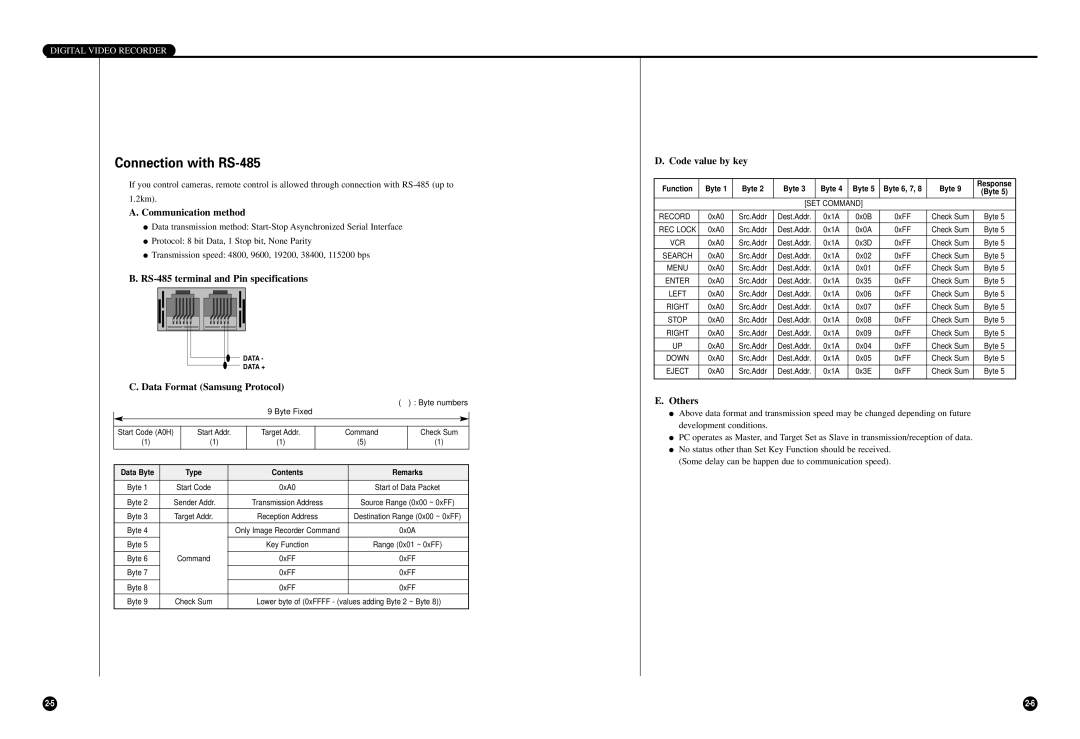
Code value by key
III. Operazioni principali
Riconoscimento del segnale video in ingresso
1Avvio del sistema
Accensione
Spegnere
10, 20 volte la velocità normale
2Visualizzazione schermate
Visione Schermo Pieno
Fare riferimento alla pagina 4-6 per i dettagli
La normale schermata Live ha questo aspetto
Visualizzazione schermata Live
Visualizzazione schermata durante la registrazione
La normale schermata di registrazione ha questo aspetto
Visualizzazione schermata in riproduzione
La normale schermata in riproduzione ha questo aspetto
IV. Menu DVR
Selezione di una voce di menu
1Vista dei menu
Attivazione del Menu Principale DVR
Modifica delle impostazioni
Esempio di impostazione nel menu modifica dell’ora
ORA
2Impostazione di data, ora e schermo
Tutti gli elementi del menu
3Impostazione registrazione
② Tipologia Segnale Allarme
4Impostazione registrazione allarme
① Rilevazione Segnale Allarme
➂ Abilitazione Buzzer
➆ Velocità Allarme
➄ Tempo PRE Allarme
➅ Tempo Post Allarme
⑧ Rilevazione Movimento
Dimensione
Sposta
6Impostazioni del sistema
① Baud Rate
② Accesso RETE/INDIRIZZO IP/GATEWAY/SUBNET Mask
Visualizzazione del menu VCR
➂ ID Utente RETE/PWD Utente Rete
Voci dei menu
1Menu VCR
Attivazione del Menu Archiviazione VCR
2ARCHIVIAZIONE Manuale
DA Lista Eventi Registrazione
Per avviare
DA Lista Eventi Allarme
DA Lista Eventi Movimento
VEL Campionamento IMM
Intervallo DI Tempo
ARCHIV. Diretta
3ARCHIVIAZIONE SU Timer
4CONFIGURAZIONE Archivio
5CONTROLLO Archivio
VI. Registrazione
① Registrazione DELL’IMMAGINE Corrente
1Registrazione di base
Registrazione di base
② Interruzione Registrazione
Disattivazione del blocco registrazione
2Blocco registrazione
Blocco registrazione
Registrazione attivata da un allarme
Impostazioni registrazione programmata
VII. Richiamo e riproduzione
4Registrazione programmata
Annullamento registrazione programmata
Ritorno al menu superiore o chiusura del menu corrente
1Menu Ricerca
Attivazione del menu DVR Ricerca
2Ricerca secondo data e ora
3Visualizzazione elenco dati registratia
4Ricerca registrazioni da allarme
5Visualizzazione elenco stato Si/No
6CONFIGURAZIONE Canale PB
7INDICAZIONE DI Sistema
VCR Sistema
HDD Sistema
HDD Rimasto
Stato Nastro
8Riproduzione di base
Per riprendere il playback, premere il tasto PLAY/STILL ❿II
9Riproduzione con VCR
Riproduzione ripetuta della sezione A-B con il DVR
Riproduzione ripetuta della sezione A-B con il VCR
VIII. Miscellanea
2Immagine dispositivo
Backup Videocassetta VCR
1Standard del prodotto
Video S-VHS
Appendice
Problemi Controllo Punti
1Controlla questi punti prima di chiamare Centro Servizio
2D e R
Domanda Risposta
Digital Video Recorder
Important Safety Instructions
Contents
Summary
Number of recording fields per second can be adjusted
2Features
Picture quality can be adjusted to 4 different levels
It has convenient search functions
3Name and Function of Each Part
Front View
Back View
Checking the Package Contents
Lift up the racks front handle and push
6Attaching/Detaching HDD
Mounting HDD
Rack into the main unit. Once
II. Connection with Other Devices
1Connection to External Devices
2Connection with Multiplexer
Connection with RS-232C
RS-232C terminal D-SUB 9 Pin and Pin specifications
Connection with PC for Use
Communication Method
Data Format Samsung Protocol
RS-485 terminal and Pin specifications
Connection with RS-485
Others
III. Basic Method to use
Recognizing incoming video signal
1Booting the System
Power On
Power Off
Write
2Basic Screen Viewing
Viewing Full Screen
Normal Live screen looks like this
Live Screen Viewing
Viewing Screen during recording
Normal recording screen looks like this
Playback screen Viewing
Normal Playback screen looks like this
IV. DVR Menus
Entering the DVR Main Menu
Changing the Settings
1Menu View
Selecting a Menu Item
Example of menu setting in case of changing time
Time
2Setting of Date, Time and Screen
Each menu item
3Record Setup
② Alarm Signal Polarity
4Alarm Record Setup
① Alarm Signal Detection
➂ Alarm Buzzer
➆ Main Alarm Picture Rate
➄ PRE Alarm Time Limit
➅ Post Alarm Time Limit
⑧ Motion Detection
Move
5Reservation Timer Setup
Size
6System Setup
➃ PAN/TILT Type Remote Control of Camera
7Communication Setup
② Network ACCESS/IP ADDRESS/GATEWAY/SUBNET Mask
Viewing VCR Menu
1VCR Menus
① Manual Archive ② Timer Archive
➂ Archive Setup ➃ Archive Check
Entering the VCR Main Menu
2MANUAL Archive
From Record Event List
From Alarm Event List
From Motion Event List
Picture Sampling Rate
Time Range
Direct Archive
3TIMER Archive
4ARCHIVE Setup
5ARCHIVE Check
VI. Record
① Current Image Record
1Basic Record
Basic Record
② Record Stop
3Alarm Record
2Record Lock
VII. Retrieval and Playback
Reservation Record Setup
Reservation Record Cancel
4Reservation Record
Returning to the Upper Menu or Exit the Current Menu
1Search Menus
Entering the DVR Search Menu
2Retrieval by Date and Time
3Recorded Data List View
4Alarm Record Retrieval
5Searching Motion Detection Recordings
7SYSTEM Indication
6PB Channel Setup
Following screen appears when you select System Indication
Tape Remain
HDD Remain
Tape Status
This shows the amount of physical tape capacity remaining
8Basic Playback
To play back again, press the PLAY/STILL❿II button
9VCR Playback
By pressing VCR button once. Then press PLAY/STILL❿II button
VCR A-B Repeat Playback
10Searching the Backed-up Data Viss
DVR A-B Repeat Playback
VIII. Others
2Appearance Drawing
Backup VCR Video Tape
Product Standards
VHS Video
Appendix
1Check Points before Call Service Center
Trouble Check Points
Question Answer
Other system to LAN to be connected to
Grabador Digital DE Video
Instrucciones importantes de seguridad
III. Método básico de utilización
Instrucciones importantes de seguridad Contenido Resumen
II. Conexión con otros dispositivos
IV. Menús del DVR
Resumen
Ofrece varias velocidades de reproducción
1Introducción
2Características
Dispone de cómodas funciones de búsqueda
3Nombre y función de cada pieza
Vista frontal
Vista posterior
Precaución
6Acoplar y quitar la unidad de disco duro
Montaje de la unidad del disco duro HDD
II. Conexión con otros dis positivos
1Conexión con dispositivos externos
2Connection with Multiplexor
REC in Entrada DE Grábacion Disk END FIN DE Disco
Conexión con RS-232C
Método de comunicación
Formato de datos Protocolo Samsung
Conexión con RS-485
Terminal RS-485 y especificaciones de las patillas
Otros
III. Método básico de utilización
Reconocimiento de la señal de vídeo entrante
1Arrancar el sistema
Encendido
Apagado
Localización de la indicación de la fecha y del tiempo
2Visualización de las pantallas básicas
Visión de Pantalla Completa
Ca a Refiera a la página 3-14 para los detalles
La pantalla en vivo normal se ve así
Visualización de la pantalla en vivo
Visualización de la pantalla durante la grabación
La pantalla de grabación normal se ve así
Visualización de la pantalla de reproducción
La pantalla de reproducción normal se ve así
IV. DVR Menús
Selección de un elemento de menú
1Vista de menús
Entrar en DVR Menú Principal
Cambio de ajustes
Ejemplo de ajuste del menú en el caso del cambio de hora
Hora
2Ajustes de fecha, hora y pantalla
Pantallas de menú
3Configuración de la grabación
② Polaridad Señal Alarma
4Configuración de grabación por alarma
① Detección Señal Alarma
➂ Pitido DE Alarma
➆ Velocidad DE Imagen
➄ Tiempo Prealarma
➅ Tiempo Postalarma
⑧ Detección DE Movimiento
Tamaño
Mover
6Configuración del sistema
➂ ID. DE USUARIO/CONTRASEÑA DE Usuario
7Configuración de la comunicación
① Velocidad DE Baudios
➃ Tipo de PAN/TILT mando a distancia de la cámara
Elementos de menú
1Menús del VCR
Entrar en VCR Menú Principal
Para iniciar la copia de
2ARCHIVO Manual
DE Lista Evento DE Grabación
Para iniciar la copia de seguridad
DE Lista Evento DE Alarma
DE Lista Evento DE Movimiento
Velocidad Muestreo Imagen
Intervalo DE Tiempo
Archivo Directo
3ARCHIVO Temporizador
Rizador
Velocidad VCR
4ARCHIVO Parámetro
GRAB. CIN. SI Prob HDD
Seleccionar Cinta
5COMPROBACIÓN DE Archivo
VI. Grabación
① Grabación DE Imagen Presente
1Grabación básica
Grabación básica
② Parada DE LA Grábacion
3GRABACIÓN POR Alarma
2Bloqueo de la grabación
VII. Búsqueda y reproducción
Configuración de grabación sincronizada
Cancelación de la grabación sincronizada
4Grabación sincronizada
Volver al menú superior o salir del menú actual
1Menús de búsqueda
Entrar en Menu DE Búsqueda
2Búsqueda por fecha y hora
3Vista de la lista de datos grabados
4Búsqueda de grabación por alarma
5Vista de la lista de los eventos de encendido/apagado
6CONFIGURACIÓN DE Canal PB
7INDICACIÓN DE Sistema
Estado DEL Sistema
Resto Disco Duro
Stop
Resto DE LA Cinta
8Reproducción básica
Puede reproducir de nuevo pulsando el botón PLAY/STILL ❿II
9Reproducción del VCR
Repetición del DVR A-B
Repetición del VCR A-B
VIII. Otros
1Especificaciones del producto
VCR Video Cinta
Los apéndices
El problema Punto de inspección
RECORD/el botón
Pregunta Respuesta