Exploded Views & Parts List
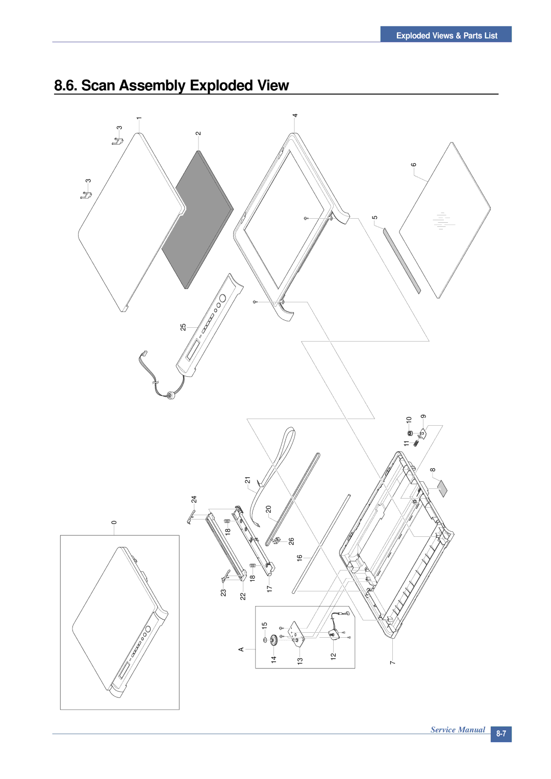
8.6. Scan Assembly Exploded View
1 | 4 |
3
3
2
6
5
25
10 | 9 |
11 |
|
8
21
24 20
0 |
|
|
|
|
|
18 |
|
|
|
|
|
|
|
| 26 |
|
|
|
|
| 16 |
|
|
|
| 18 |
|
|
|
23 | 22 | 17 |
|
|
|
|
| 15 |
|
|
|
| A |
|
| 12 |
|
|
| 14 | 13 | 7 |
Service Manual | |
|
Exploded Views & Parts List
1 | 4 |
3
3
2
6
5
25
10 | 9 |
11 |
|
8
21
24 20
0 |
|
|
|
|
|
18 |
|
|
|
|
|
|
|
| 26 |
|
|
|
|
| 16 |
|
|
|
| 18 |
|
|
|
23 | 22 | 17 |
|
|
|
|
| 15 |
|
|
|
| A |
|
| 12 |
|
|
| 14 | 13 | 7 |
Service Manual | |
|