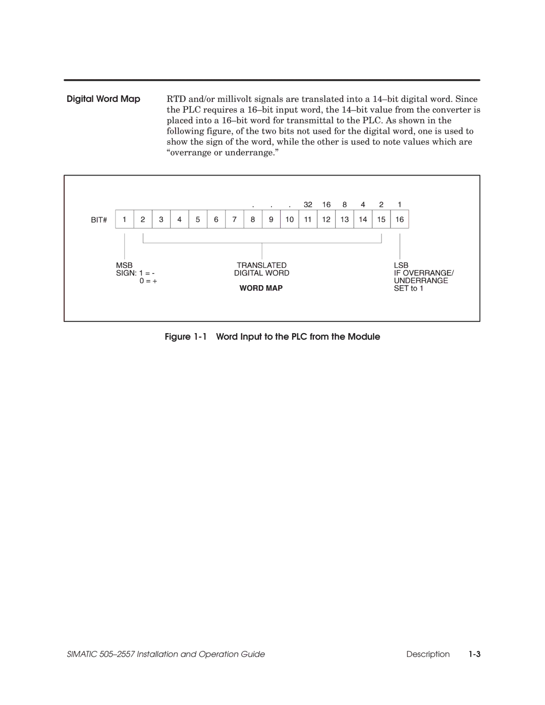
Digital Word Map RTD and/or millivolt signals are translated into a 14±bit digital word. Since the PLC requires a 16±bit input word, the 14±bit value from the converter is placed into a 16±bit word for transmittal to the PLC. As shown in the following figure, of the two bits not used for the digital word, one is used to show the sign of the word, while the other is used to note values which are ªoverrange or underrange.º
Figure 1-1 Word Input to the PLC from the Module
SIMATIC 505±2557 Installation and Operation Guide | Description |