Peak and Valley | Outputs Y28 and Y29 are used to reset the valley or peak hold functions. | |
Hold Reset | The operation during reset is dependent on whether the hold function is | |
| enabled for each individual channel. | |
| Figure | |
| reset. |
|
|
| |
| Peak or Valley Hold Function | |
| Enabled | Reset to current input value |
| Disabled | Reset to zero |
|
|
|
| Figure |
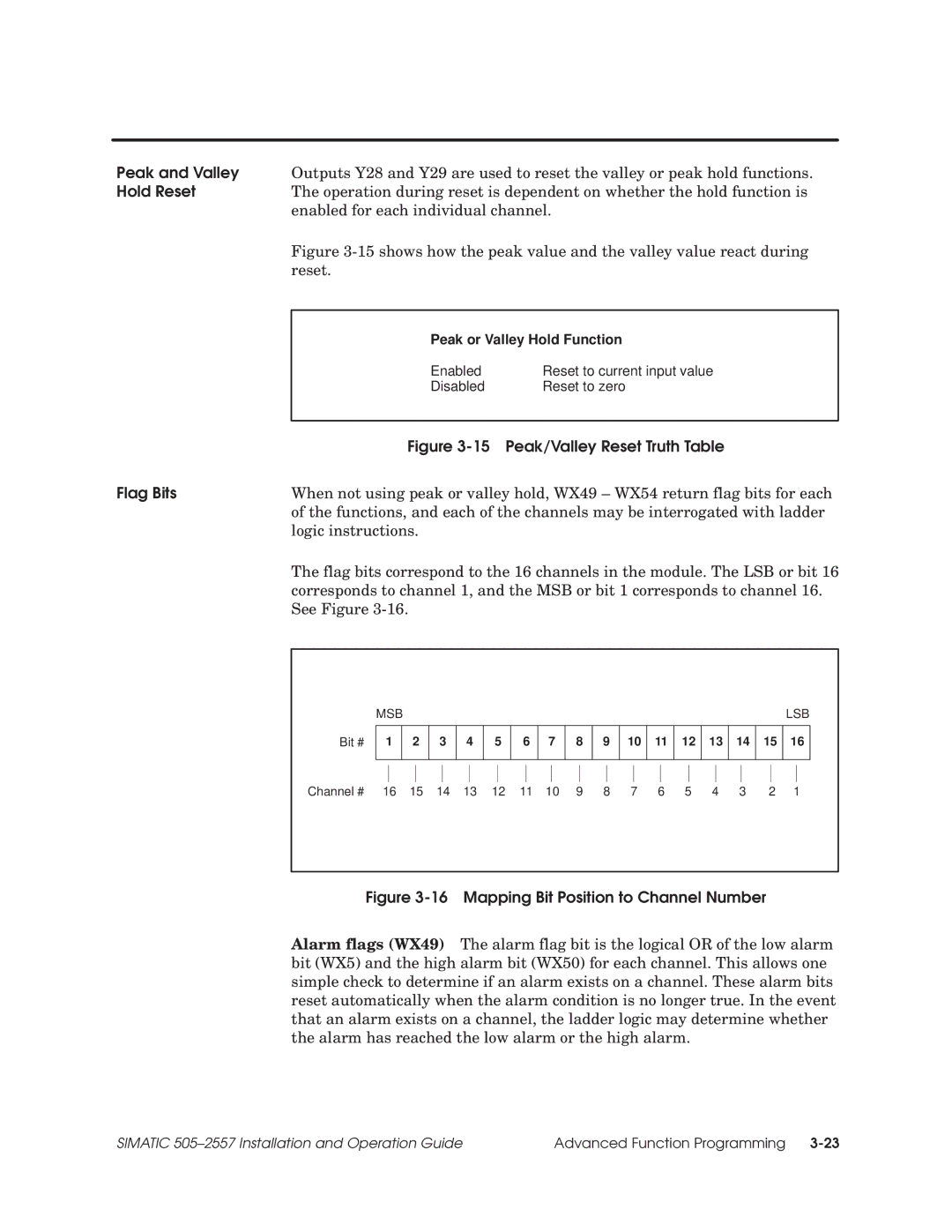
Flag Bits | When not using peak or valley hold, WX49 ± WX54 return flag bits for each |
| of the functions, and each of the channels may be interrogated with ladder |
| logic instructions. |
| The flag bits correspond to the 16 channels in the module. The LSB or bit 16 |
| corresponds to channel 1, and the MSB or bit 1 corresponds to channel 16. |
| See Figure |
Bit #
MSB |
|
|
|
|
|
|
|
|
|
|
|
|
|
| LSB | |
|
|
|
|
|
|
|
|
|
|
|
|
|
|
|
|
|
1 |
| 2 | 3 | 4 | 5 | 6 | 7 | 8 | 9 | 10 | 11 | 12 | 13 | 14 | 15 | 16 |
|
|
|
|
|
|
|
|
|
|
|
|
|
|
|
|
|
Channel # 16 15 14 13 12 11 10 9 8 7 6 5 4 3 | 2 1 |
Figure 3-16 Mapping Bit Position to Channel Number
Alarm flags (WX49) The alarm flag bit is the logical OR of the low alarm bit (WX5) and the high alarm bit (WX50) for each channel. This allows one simple check to determine if an alarm exists on a channel. These alarm bits reset automatically when the alarm condition is no longer true. In the event that an alarm exists on a channel, the ladder logic may determine whether the alarm has reached the low alarm or the high alarm.
SIMATIC 505±2557 Installation and Operation Guide | Advanced Function Programming |