Internal Register Structures (continued)
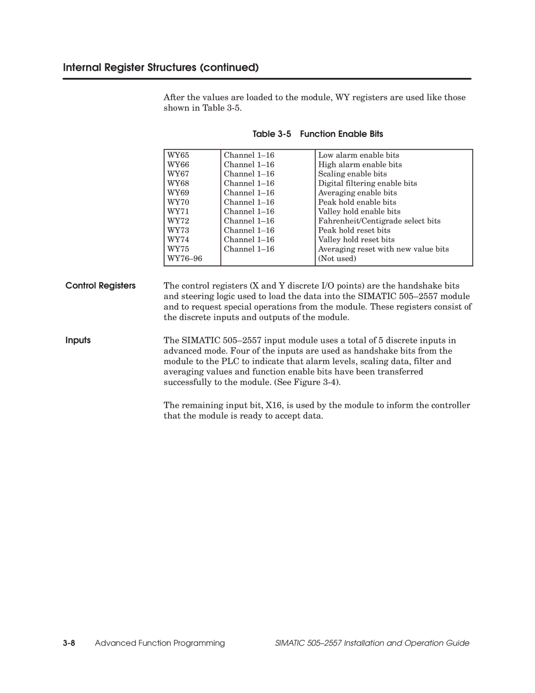
After the values are loaded to the module, WY registers are used like those shown in Table
Table 3-5 Function Enable Bits
WY65 | Channel 1±16 | Low alarm enable bits |
WY66 | Channel 1±16 | High alarm enable bits |
WY67 | Channel 1±16 | Scaling enable bits |
WY68 | Channel 1±16 | Digital filtering enable bits |
WY69 | Channel 1±16 | Averaging enable bits |
WY70 | Channel 1±16 | Peak hold enable bits |
WY71 | Channel 1±16 | Valley hold enable bits |
WY72 | Channel 1±16 | Fahrenheit/Centigrade select bits |
WY73 | Channel 1±16 | Peak hold reset bits |
WY74 | Channel 1±16 | Valley hold reset bits |
WY75 | Channel 1±16 | Averaging reset with new value bits |
WY76±96 |
| (Not used) |
|
|
|
Control Registers | The control registers (X and Y discrete I/O points) are the handshake bits |
| and steering logic used to load the data into the SIMATIC 505±2557 module |
| and to request special operations from the module. These registers consist of |
| the discrete inputs and outputs of the module. |
Inputs | The SIMATIC 505±2557 input module uses a total of 5 discrete inputs in |
| advanced mode. Four of the inputs are used as handshake bits from the |
| module to the PLC to indicate that alarm levels, scaling data, filter and |
| averaging values and function enable bits have been transferred |
| successfully to the module. (See Figure |
| The remaining input bit, X16, is used by the module to inform the controller |
| that the module is ready to accept data. |
Advanced Function Programming | SIMATIC 505±2557 Installation and Operation Guide |