2.2Wiring the Input Connectors
RTD input signals are accepted through a 64 position fixed connector with wire press in terminals located on the front of the module. Consult the RTD manufacturer's recommendations for selecting the input wire type and size. The connector will accept 18 to 30 AWG wire.
The SIMATIC 505±2557 uses a fixed connector to terminate field wiring. This is used because the chemistry of a removable connector may have an adverse effect on the accuracy of the measurement. Siemens has carefully selected a connector that minimizes this effect.
Refer to Figure
Remove wire by depressing spring lever to remove tension and then remove lead wire. (See Figure
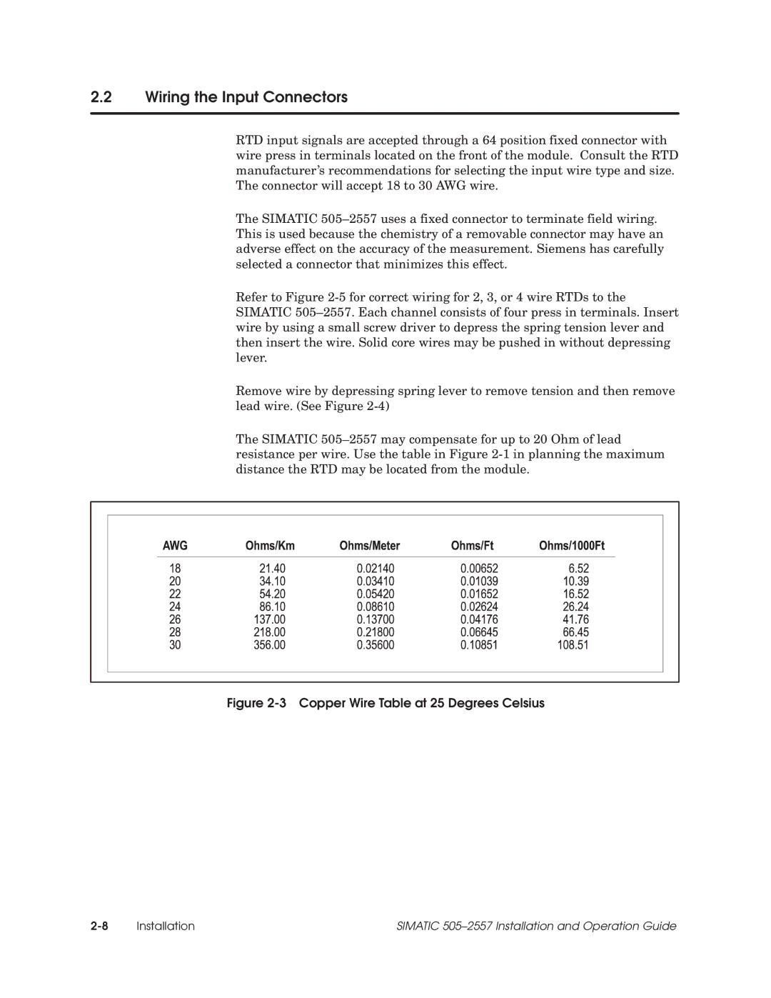
The SIMATIC 505±2557 may compensate for up to 20 Ohm of lead resistance per wire. Use the table in Figure
Figure 2-3 Copper Wire Table at 25 Degrees Celsius
Installation | SIMATIC 505±2557 Installation and Operation Guide |