Internal Register Structures (continued)
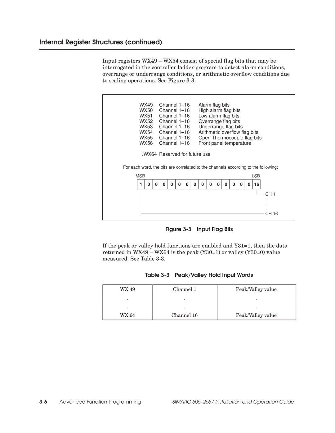
Input registers WX49 ± WX54 consist of special flag bits that may be interrogated in the controller ladder program to detect alarm conditions, overrange or underrange conditions, or arithmetic overflow conditions due to scaling operations. See Figure
WX49 | Channel 1±16 Alarm flag bits |
WX50 | Channel 1±16 High alarm flag bits |
WX51 | Channel 1±16 Low alarm flag bits |
WX52 | Channel 1±16 Overrange flag bits |
WX53 | Channel 1±16 Underrange flag bits |
WX54 | Channel 1±16 Arithmetic overflow flag bits |
WX55 | Channel 1±16 Open Thermocouple flag bits |
WX56 | Channel 1±16 Front panel temperature |
.WX64 | Reserved for future use |
For each word, the bits are correlated to the channels according to the following:
MSB |
|
|
|
|
|
|
|
|
|
|
|
|
|
| LSB | |||||||
| 1 |
| 0 | 0 | 0 | 0 | 0 | 0 | 0 | 0 | 0 | 0 | 0 | 0 | 0 | 0 |
| 16 |
|
| ||
|
|
|
|
|
|
|
|
|
|
|
|
|
|
|
|
|
|
|
|
|
| CH 1 |
|
|
|
|
|
|
|
|
|
|
|
|
|
|
|
|
|
|
|
|
|
| |
|
|
|
|
|
|
|
|
|
|
|
|
|
|
|
|
|
|
|
|
|
| |
|
|
|
|
|
|
|
|
|
|
|
|
|
|
|
|
|
|
|
|
|
| |
|
|
|
|
|
|
|
|
|
|
|
|
|
|
|
|
|
| . | ||||
|
|
|
|
|
|
|
|
|
|
|
|
|
|
|
|
|
| . | ||||
|
|
|
|
|
|
|
|
|
|
|
|
|
|
|
|
|
| . | ||||
|
|
|
|
|
|
|
|
|
|
|
|
|
|
|
|
|
|
|
|
|
| CH 16 |
|
|
|
|
|
|
|
|
|
|
|
|
|
|
|
|
|
|
|
|
|
| |
Figure 3-3 Input Flag Bits
If the peak or valley hold functions are enabled and Y31=1, then the data returned in WX49 ± WX64 is the peak (Y30=1) or valley (Y30=0) value measured. See Table
Table 3-3 Peak/Valley Hold Input Words
WX 49
.
.
WX 64
Channel 1
.
.
Channel 16
Peak/Valley value
.
.
Peak/Valley value
Advanced Function Programming | SIMATIC 505±2557 Installation and Operation Guide |
