Ground at One End Only |
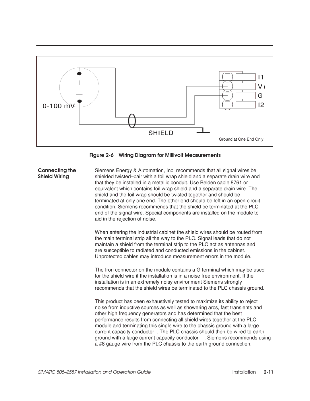
Figure 2-6 Wiring Diagram for Millivolt Measurements
Connecting the Siemens Energy & Automation, Inc. recommends that all signal wires be
Shield Wiring shielded twisted±pair with a foil wrap shield and a separate drain wire and that they be installed in a metallic conduit. Use Belden cable 8761 or equivalent which contains foil wrap shield and a separate drain wire. The shield and the foil wrap should be twisted together and should be terminated at only one end. The other end should be left in an open circuit condition. Siemens recommends that the shield be terminated at the PLC end of the signal wire. Special components are installed on the module to aid in the rejection of noise.
When entering the industrial cabinet the shield wires should be routed from the main terminal strip all the way to the PLC. Signal leads that do not maintain a shield from the terminal strip to the PLC act as antennas and are susceptible to radiated and conducted emissions in the cabinet. Unprotected cables may introduce measurement errors in the module.
The fron connector on the module contains a G terminal which may be used for the shield wire if the installation is in a noise free environment. If the installation is in an extremely noisy environment Siemens strongly recommends that the shield wires be terminated to the PLC chassis ground.
This product has been exhaustively tested to maximize its ability to reject noise from inductive sources as well as showering arcs, fast transients and other high frequency generators and has determined that the best performance results from connecting all shield wires together at the PLC module and terminating this single wire to the chassis ground with a large current capacity conductor. The PLC chassis should then be wired to earth ground with a large current capacity conductor. Siemens recommends using a #8 gauge wire from the PLC chassis to the earth ground connection.
SIMATIC 505±2557 Installation and Operation Guide | Installation |
