Manuals
/
Siemens
/
Musical Instruments & Equipment
/
Drums
Siemens
505-2557
installation and operation guide
Models:
505-2557
1
59
68
68
Download
68 pages
28.88 Kb
56
57
58
59
60
61
62
63
Troubleshooting
Specifications
Signals
Default Values
Wiring the Input Connectors
Configuring
Hold Reset
Setting the Module
Resolution
Temperature or
Page 59
Image 59
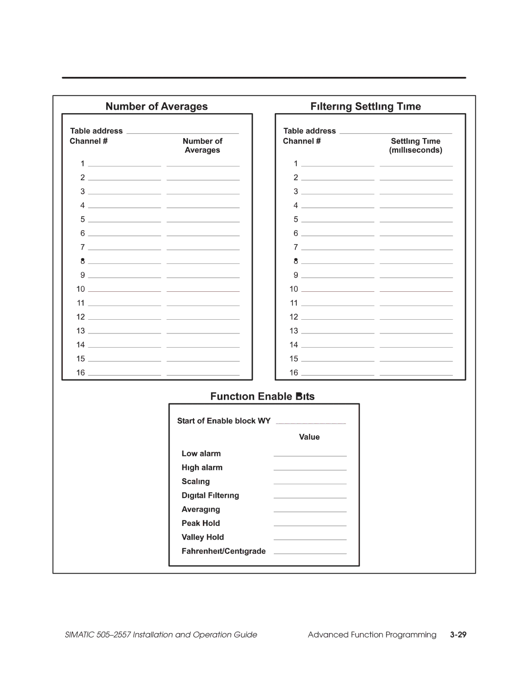
SIMATIC 505±2557 Installation and Operation Guide
Advanced Function Programming
3-29
Page 58
Page 60
Page 59
Image 59
Page 58
Page 60
Contents
Simatic
Copyright 1998 by Siemens Energy & Automation, Inc
Manual Publication History
List of Effective Pages
Contents
Iv Contents
List of Figures
List of Tables
Preface
Approval
Agency Approvals
European
Community CE
100 Ohm, 10 Ohm, 120 Ohm RTDs, or Millivolt Inputs
Description
Operating Modes
Word Input to the PLC from the Module
Scale Units
RTD Input to Digital Conversion
Out-of-Range Input
Signals
Effect
Effect of Voltage Input 10 Ohm Copper
Input Resolution
Resolution
Selecting 2 and 3 Wire or 4 Wire Operation
Installing and Configuring the Module
Calculating the I/O Base Power Budget
Installing and Configuring the Module
Configuring
Millivolt Input
Temperature or
Selecting
Selecting Data
Selecting Degrees
Celsius or
Fahrenheit
Configuration Jumper Locations
Base
Inserting
Module Into
Copper Wire Table at 25 Degrees Celsius
Wiring the Input Connectors
Press In Wiring Connector
Wiring Diagram for 2, 3, or 4 Wire RTD
Wiring Diagram for Millivolt Measurements
Cable Grounding
Example I/O Configuration Chart
Advanced Function Programming
Advanced
Advanced Software Functions
Introduction
Overview
Jumper
Setting the Module
Configuration
Memory
Logging
Controller I/O
Input Channel Data
Internal Register Structures
Input and Output Register Offsets
Input Registers
Peak/Valley Hold Input Words
Input Flag Bits
Averaging
Output Data Registers
Inputs
Function Enable Bits
Control Registers
Discrete Handshake Inputs
Data Identification Bits
Outputs
Data Loading Process
Loading Data into the Simatic 505±2557 Module
Sample Low and High Alarm Setpoints
Identifying the Data Being Transferred
11 Enabling the Functions Loaded
Loading Programs into the I/O Module
13 Startup Relay Ladder Logic
Page
Timing Constraints
When Using
Timing Overhead for Functions Enabled
Timing Considerations
Additional Information about Each Function
Default Values
Default Function Values
Default Function Values for Simatic 505±2557
Degrees Fahrenheit
Alarm Setpoints
Degrees
Centigrade or
Digital Filtering
Hold
Averaging
Peak and Valley
Flag Bits
Hold Reset
Precedence
Function
Troubleshooting
Symptom Probable Cause Corrective Action
10 Troubleshooting Flow Diagram
17 I/O Register Quick Reference
I/O Register Quick Reference
Or K Memory Configuration Tables
Page
Addressing Worksheet
18 Open RTD Status Bits
Items Unique to the Simatic 505±2557 Module
Troubleshooting
Table B-1 Specifications
Specifications
Specifications subject to change without notice
Jumper Settings Log Sheet
Customer Response
Business Reply Mail
Top
Page
Image
Contents