Internal Register Structures (continued)
The following steps explain how data is loaded into the SIMATIC 505±2557 module.
1.V- or
V1 | 100 | V17 | 20,100 |
V2 | 200 | V18 | 20,200 |
V3 | 300 | V19 | 20,300 |
V4 | 400 | V20 | 20,400 |
V5 | 500 | V21 | 20,500 |
V6 | 600 | V22 | 20,600 |
V7 | 700 | V23 | 20,700 |
V8 | 800 | V24 | 20,800 |
V9 | 900 | V25 | 20,900 |
V10 | 1000 | V26 | 21,000 |
V11 | 1100 | V27 | 22,000 |
V12 | 1200 | V28 | 23,000 |
V13 | 1300 | V29 | 24,000 |
V14 | 1400 | V30 | 25,000 |
V15 | 1500 | V31 | 26,000 |
V16 | 1600 | V32 | 27,000 |
Figure 3-7 Sample Low and High Alarm Setpoints
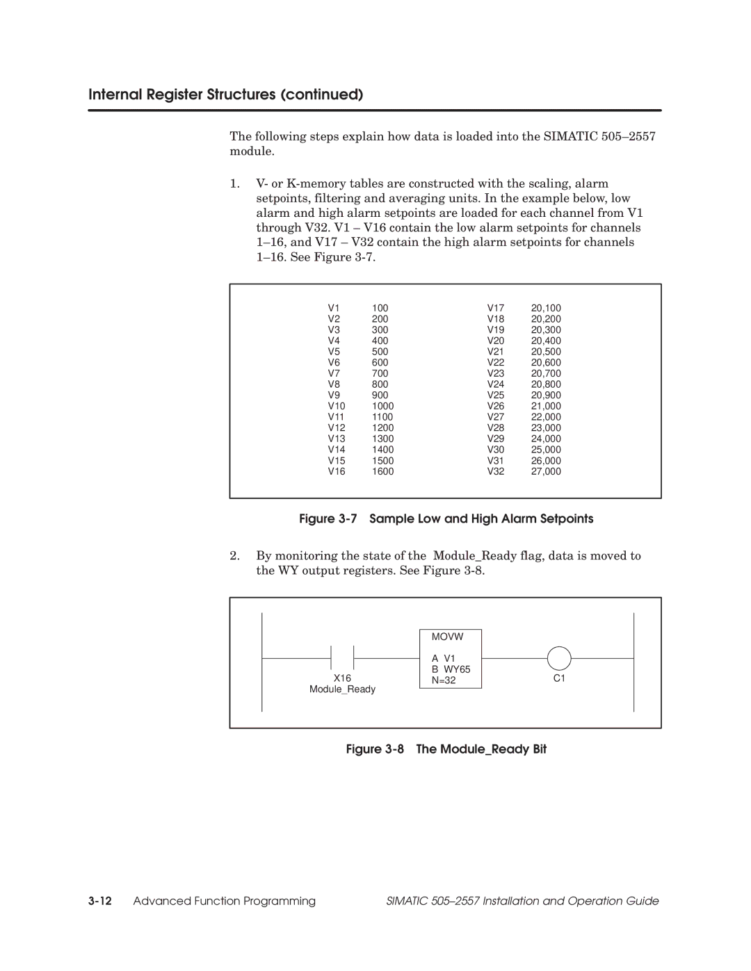
2.By monitoring the state of the Module_Ready flag, data is moved to the WY output registers. See Figure
MOVW
A V1
B WY65
X16N=32C1
Module_Ready
Figure 3-8 The Module_Ready Bit
SIMATIC 505±2557 Installation and Operation Guide |