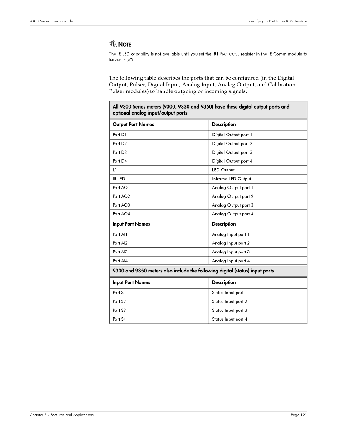
9300, 9350, 9330 specifications
Siemens has made significant advancements in the field of manufacturing and industrial automation with its range of products, particularly focusing on the Siemens 9330, 9350, and 9300 series. These models are designed to optimize performance, increase efficiency, and ensure reliability in various industrial applications.The Siemens 9330 model is known for its robust construction and versatility. It supports a variety of communication protocols, making integration into existing systems easy. One of the key features of the 9330 is its high processing speed. This enables it to handle complex operations in real time, ensuring minimal downtime. Additionally, its modular design allows for easy expansion, catering to the specific needs of different industries.
The Siemens 9350 takes automation to the next level with advanced functionalities. It incorporates cutting-edge technologies such as AI-driven diagnostics and predictive maintenance features. These technologies gather data from various sensors, providing operators with valuable insights into machine performance. The 9350 also features enhanced security measures, ensuring data protection and minimizing risks associated with cyber threats. The blend of flexibility and reliability makes it suitable for critical applications across sectors like manufacturing and energy.
The Siemens 9300 series is designed for high-precision tasks, primarily focusing on automation in manufacturing environments. This series is equipped with sophisticated motion control capabilities, allowing for precise positioning and motion synchronization. Users benefit from its user-friendly interfaces and simplified programming, which streamline the setup process and reduce operational complexities. The energy-efficient design of the 9300 series contributes to reduced operational costs, aligning with modern sustainability goals.
In summary, the Siemens 9330, 9350, and 9300 series represent the pinnacle of industrial automation technology. Each model comes with unique features and capabilities tailored to specific requirements in the manufacturing landscape. The advancements in AI, energy efficiency, security, and modular design reflect Siemens' commitment to providing high-quality solutions that enhance productivity and reduce operational risks. Whether an enterprise is looking to upgrade existing systems or implement new technologies, these models from Siemens offer the potential for significant improvement in operational efficiency.

