Customizing Frameworks in Designer

9300 Series User’s Guide


Accessing module outputs

The cursor looks like this when a linking operation is in progress:

Accessing module inputs

You can link modules that reside on different nodes, provided that you are linking between software nodes, or from a meter to a software node. You cannot link modules between meters. The following section describes how to link modules that reside on the same node. Refer to the ION Programmer’s Reference or the online WinPM.Net Help for instructions if you want to link modules that reside on different nodes.

Follow the steps below to link modules on the meter:

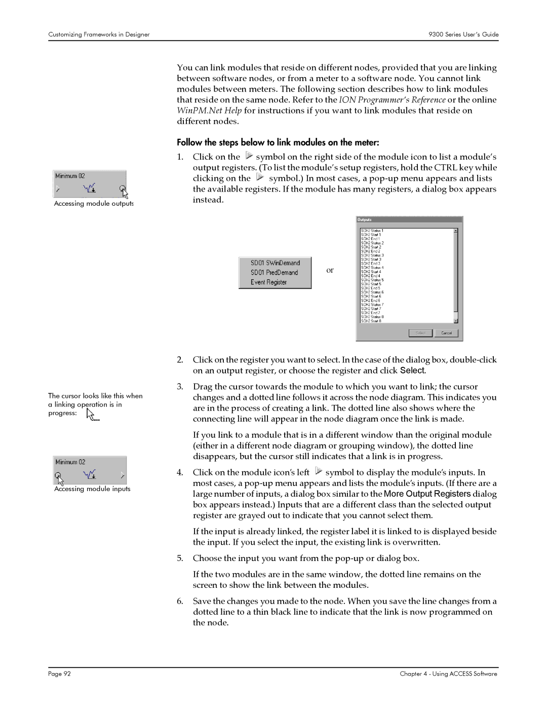
1.Click on the symbol on the right side of the module icon to list a module’s

output registers. (To list the module’s setup registers, hold the CTRL key while clicking on the symbol.) In most cases, a pop-up menu appears and lists the available registers. If the module has many registers, a dialog box appears instead.

or

2.Click on the register you want to select. In the case of the dialog box, double-click on an output register, or choose the register and click Select.

3.Drag the cursor towards the module to which you want to link; the cursor changes and a dotted line follows it across the node diagram. This indicates you are in the process of creating a link. The dotted line also shows where the connecting line will appear in the node diagram once the link is made.

If you link to a module that is in a different window than the original module (either in a different node diagram or grouping window), the dotted line disappears, but the cursor still indicates that a link is in progress.

4.Click on the module icon’s left symbol to display the module’s inputs. In

most cases, a pop-up menu appears and lists the module’s inputs. (If there are a large number of inputs, a dialog box similar to the More Output Registers dialog box appears instead.) Inputs that are a different class than the selected output register are grayed out to indicate that you cannot select them.

If the input is already linked, the register label it is linked to is displayed beside the input. If you select the input, the existing link is overwritten.

5.Choose the input you want from the pop-up or dialog box.

If the two modules are in the same window, the dotted line remains on the screen to show the link between the modules.

6.Save the changes you made to the node. When you save the line changes from a dotted line to a thin black line to indicate that the link is now programmed on the node.

Page 92

Chapter 4 - Using ACCESS Software

Page 92
Image 92
Siemens 9330, 9350, 9300 manual Follow the steps below to link modules on the meter

9300, 9350, 9330 specifications

Siemens has made significant advancements in the field of manufacturing and industrial automation with its range of products, particularly focusing on the Siemens 9330, 9350, and 9300 series. These models are designed to optimize performance, increase efficiency, and ensure reliability in various industrial applications.

The Siemens 9330 model is known for its robust construction and versatility. It supports a variety of communication protocols, making integration into existing systems easy. One of the key features of the 9330 is its high processing speed. This enables it to handle complex operations in real time, ensuring minimal downtime. Additionally, its modular design allows for easy expansion, catering to the specific needs of different industries.

The Siemens 9350 takes automation to the next level with advanced functionalities. It incorporates cutting-edge technologies such as AI-driven diagnostics and predictive maintenance features. These technologies gather data from various sensors, providing operators with valuable insights into machine performance. The 9350 also features enhanced security measures, ensuring data protection and minimizing risks associated with cyber threats. The blend of flexibility and reliability makes it suitable for critical applications across sectors like manufacturing and energy.

The Siemens 9300 series is designed for high-precision tasks, primarily focusing on automation in manufacturing environments. This series is equipped with sophisticated motion control capabilities, allowing for precise positioning and motion synchronization. Users benefit from its user-friendly interfaces and simplified programming, which streamline the setup process and reduce operational complexities. The energy-efficient design of the 9300 series contributes to reduced operational costs, aligning with modern sustainability goals.

In summary, the Siemens 9330, 9350, and 9300 series represent the pinnacle of industrial automation technology. Each model comes with unique features and capabilities tailored to specific requirements in the manufacturing landscape. The advancements in AI, energy efficiency, security, and modular design reflect Siemens' commitment to providing high-quality solutions that enhance productivity and reduce operational risks. Whether an enterprise is looking to upgrade existing systems or implement new technologies, these models from Siemens offer the potential for significant improvement in operational efficiency.