Teleperm M
Brief description
Introduction
Functions of the AS 235 system
Configuring
General system data
System data
Technical data of automation systems
Or user-configured with own
System architecture
Configuring
Performance characteristics
Operation and monitoring
TML language
Scope of performance
Redundancy with the AS 235 H automation system
Redundancy with AS 235 H
Important note
Blocks for analog and digital processing
Configuring
Standard function blocks
Standard function blocks
Data blocks
Blocks for signal exchange via CS
Type Designation Function For modules with Order No
Driver blocks for I/O modules
Driver blocks for I/O modules with standardized display
Driver blocks for configurable Teleperm ME I/O modules
Organization blocks
Output blocks for printer and process monitor
System architecture
Performance characteristics
Summary of system properties
Redundancy with AS 235 H
Configuring
Data blocks
Driver blocks for I/O modules
Driver blocks for configurable Teleperm ME I/O modules
Output blocks for printer and process monitor
ES 100 K
Connection diagrams
AS 235 H
AS 235 K
General
General
Basic unit
Basic cabinet
AS 235 automation system
Basic cabinet
Extension units
Standard I/O devices
Bus components
Power supply components
Basic cabinet
Ordering data for basic cabinet
Ordering data
AS 235 automation system
See page 6/6
Options for basic cabinet
Options for AS 235 basic Cabinet
6DS9 002-8BB
Options for AS 235 extension Cabinet
Extension cabinet
Extension cabinet
Extension cabinet
AS 235 H automation system
AS 235 H
AS 235 H automation system, design
6DS3 305-8BA
Example of redundancy with
Redundant process I/Os
Interface modules for 20-m local bus N-AS
AS 235 H automation system
Options for AS 235 H basic Cabinet
AS 235 H extension cabinet
Options for AS 235 H exten Sion cabinet
Ordering data for extension cabinet
AS 235 H automation
System Extension cabinet
Basic system
AS 235 K
Basic system
AS 235 K automation system
AS 235 K automation system, design
Interface module for ES 100 K
System
Housing
Ordering data for AS 235 K
AS 235 K automation
ES 100 K extension system
ES 100 K
ES 100 K extension system
ES 100 K extension
Ordering data for ES 100 K
ES 100 K options
Standard cabinets
Standard cabinets and accessories
Standard cabinets and accessories
System cabinet accessories
Ordering data for system cabinet accessories
Permissible thermal loading
Configuring values for thermal load
Standard cabinet with heat exchanger
Standard cabinets IP 20 without heat exchanger
Technical data
Design
12 Standard cabinet with heat exchanger
Standard cabinets IP 54 with heat exchanger
Process connection systems
Connections for process signal cables
Process connection systems
Process connection systems
Connection diagrams for standard I/O devices to AS AS 235 K
Connection diagrams
Standard I/O devices to AS 235 / AS 235 K
Connection of personal computer
Connection of personal computer
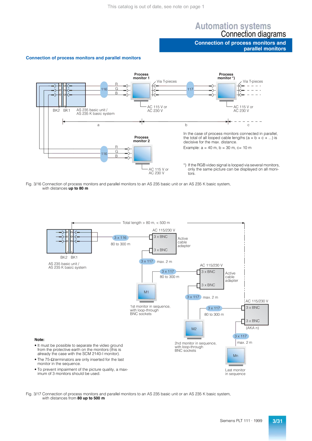
Connection of process monitors and parallel monitors
Connection of process monitors and parallel monitors
Standard I/O devices to AS 235 H
Connection diagrams for standard I/O devices to AS 235 H
Connection diagrams
Connecting cable Plug Cable Max. cable Order No From Length
Summary of connecting cables
Function modules
Signal modules
Proportioning Counter modules
Summary
Configurable I/O modules
General technical data
Selection criteria for I/O modules
Power supply, earthing
Lightning protection with distributed configuration
Modules from other systems
Closed-loop control modules
Function modules
Closed-loop control modules
Function modules
Signal modules
Signal modules
Analog input and output modules
Binary output module with 16 relays, 6DS1 605-8BA
Binary input and output modules
Binary input and output modules
Binary input module, testable, 6DS1 618-8CA
Metering pulse input module with 8 channels, 6DS1 607-8AB
STRUK-AS 220 EA configuring program
Proportioning and counter modules
Proportioning counter module, metering pulse input module
Modules which can be used on the I/O bus
Modules which can be used on the I/O bus
Explanations for the column Release
Explanations for the column Remarks
6DS1 342-1BD With S5KE
PBT 65 process operation keyboard
Mode of operation
Test mode
Operation unit
Configuring keyboard
Configuring unit
Configuring keyboard
Floppy disks
Mini floppy disk unit
Mini floppy disk unit
Mini floppy disk unit 6DS3 900-8AE
Bus communication
Application
Application
Local range
Remote range
Design
Single remote bus
Redundant remote bus
Connector board AF Remote bus
Connection distributor AV
Bus converter Ul
Bus configurations, examples
Bus configurations
Application Other conditions Connecting cables
Connecting cables for 20-m local bus
Connecting cables
Connecting cables for remote bus
Central controllers
Expansion units
Simatic S5 I/Os ET 100U
Coupling of other systems
Interface modules for coupling with other systems, summary
Parallel coupling with S5-115U I/O modules
Simatic S5 expansion units
Parallel coupling with Simatic S5-115U I/O modules
Digital input/output modules
Simatic S5-115U I/O modules appropriate for coupling
Digital input modules
Digital output modules
Parallel coupling with Simatic S5-135U/155U I/O modules
Parallel coupling with S5-135U/155U I/O modules
Simatic S5-135U/155U I/O modules appropriate for coupling
Interface module for Simatic S5 expansion units
Interface module for Simatic S5 expansion units
Serial coupling With Simatic S5/S7 central controllers
Simatic S5/S7 central controllers
Serial coupling with Simatic S5/S7 central controllers
Interface module for Simatic S5/S7 central controllers
Interface module for Simatic S5/S7 central controllers
Serial coupling with Simatic S5 I/Os
Simatic S5 I/Os / ET 100U
Exi modules
ET 100U I/O modules appropriate for coupling
Interface module for ET 100U
Interface module for ET 100U
Ordering information
Ordering of complete systems AS 235 standard configuration
Ordering of options

![]() AC 115 V or
AC 115 V or![]() AC 115 V or
AC 115 V or AC 115 V or AC 230 V