3 Installation and Commissioning
3 Installation and Commissioning
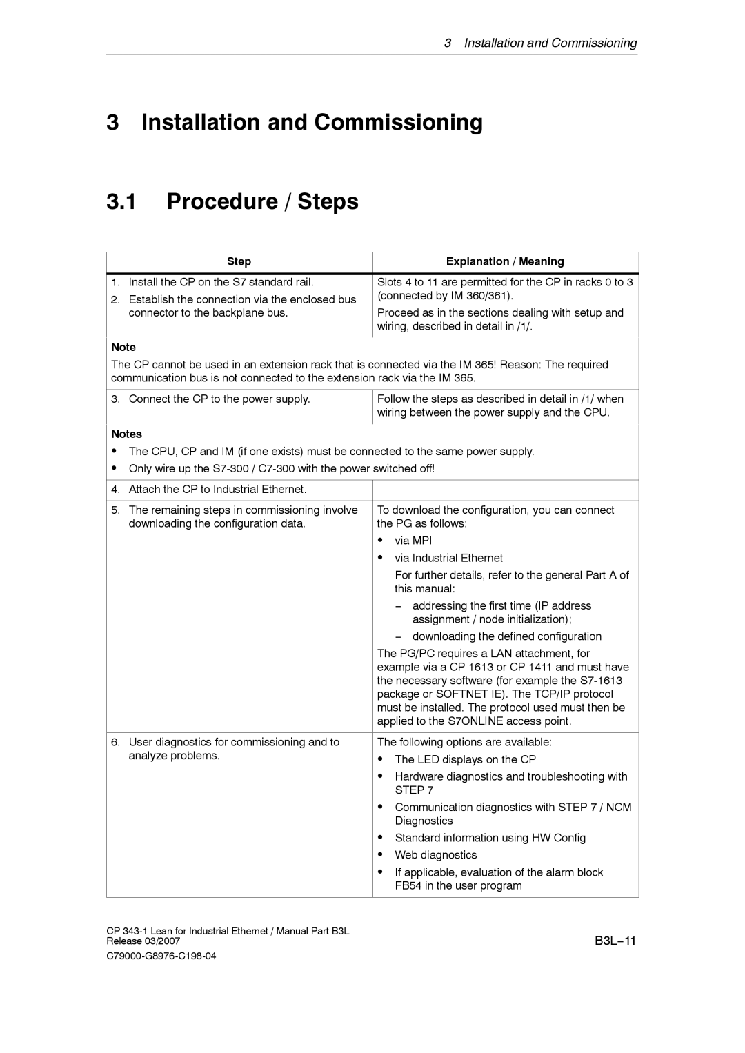
3.1Procedure / Steps
| Step | Explanation / Meaning |
|
|
|
1. | Install the CP on the S7 standard rail. | Slots 4 to 11 are permitted for the CP in racks 0 to 3 |
2. | Establish the connection via the enclosed bus | (connected by IM 360/361). |
| ||
| connector to the backplane bus. | Proceed as in the sections dealing with setup and |
|
| wiring, described in detail in /1/. |
|
|
|
Note
The CP cannot be used in an extension rack that is connected via the IM 365! Reason: The required communication bus is not connected to the extension rack via the IM 365.
3. Connect the CP to the power supply.
Notes
Follow the steps as described in detail in /1/ when wiring between the power supply and the CPU.
SThe CPU, CP and IM (if one exists) must be connected to the same power supply.
SOnly wire up the
4. Attach the CP to Industrial Ethernet. |
|
|
|
| |
5. The remaining steps in commissioning involve | To download the configuration, you can connect | |
downloading the configuration data. | the PG as follows: | |
| S | via MPI |
| S | via Industrial Ethernet |
|
| For further details, refer to the general Part A of |
|
| this manual: |
|
| − addressing the first time (IP address |
|
| assignment / node initialization); |
|
| − downloading the defined configuration |
| The PG/PC requires a LAN attachment, for | |
| example via a CP 1613 or CP 1411 and must have | |
| the necessary software (for example the | |
| package or SOFTNET IE). The TCP/IP protocol | |
| must be installed. The protocol used must then be | |
| applied to the S7ONLINE access point. | |
|
| |
6. User diagnostics for commissioning and to | The following options are available: | |
analyze problems. | S | The LED displays on the CP |
| ||
| S Hardware diagnostics and troubleshooting with | |
|
| STEP 7 |
| S Communication diagnostics with STEP 7 / NCM | |
|
| Diagnostics |
| S Standard information using HW Config | |
| S | Web diagnostics |
| S If applicable, evaluation of the alarm block | |
|
| FB54 in the user program |
|
|
|
CP |
| B3L−11 |
Release 03/2007 |
| |