4 Creating Project Files—PLC to Devices
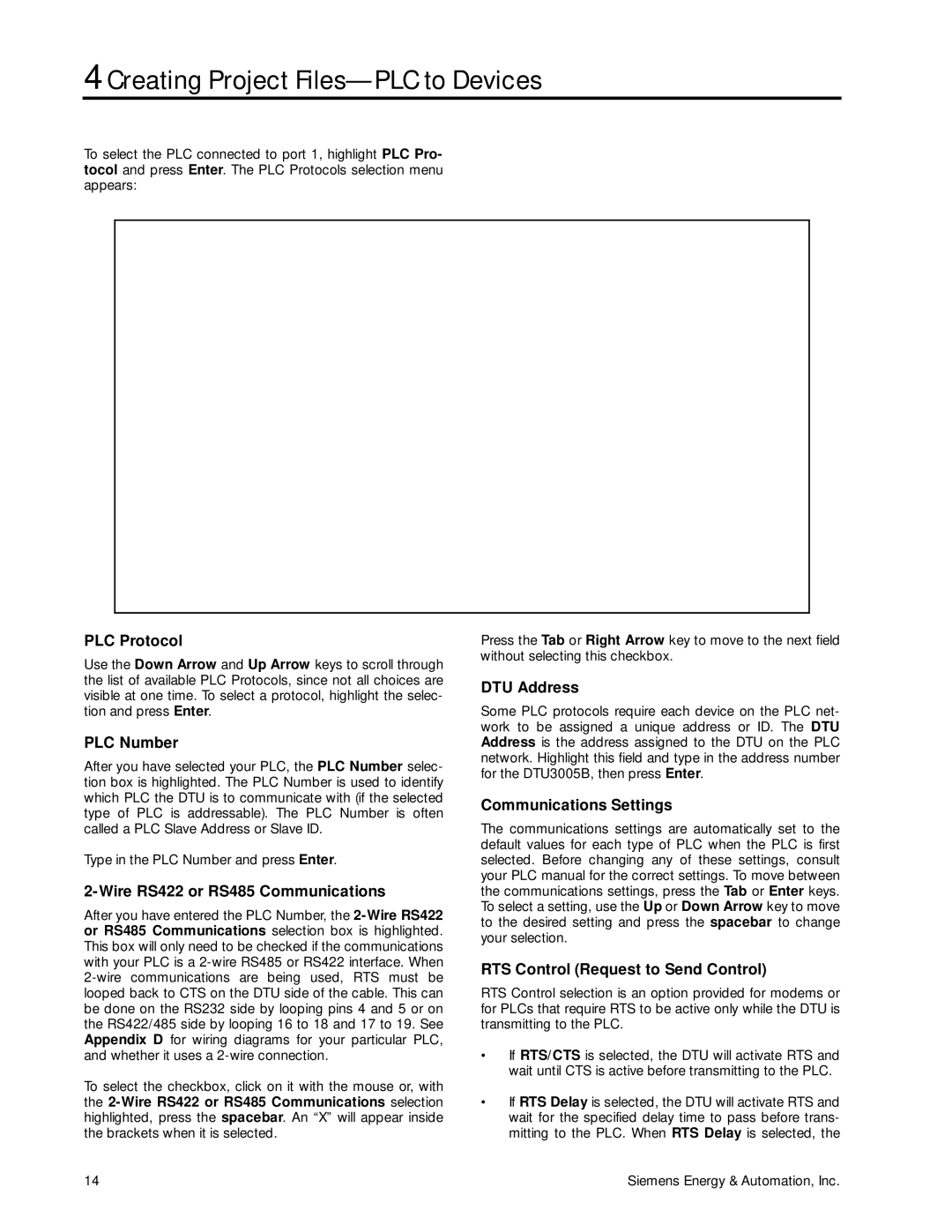
To select the PLC connected to port 1, highlight PLC Pro- tocol and press Enter. The PLC Protocols selection menu appears:
PLC Protocol | Press the Tab or Right Arrow key to move to the next field | |
Use the Down Arrow and Up Arrow keys to scroll through | without selecting this checkbox. | |
| ||
the list of available PLC Protocols, since not all choices are | DTU Address | |
visible at one time. To select a protocol, highlight the selec- | ||
| ||
tion and press Enter. | Some PLC protocols require each device on the PLC net- | |
PLC Number | work to be assigned a unique address or ID. The DTU | |
Address is the address assigned to the DTU on the PLC | ||
After you have selected your PLC, the PLC Number selec- | network. Highlight this field and type in the address number | |
for the DTU3005B, then press Enter. | ||
tion box is highlighted. The PLC Number is used to identify | ||
| ||
which PLC the DTU is to communicate with (if the selected | Communications Settings | |
type of PLC is addressable). The PLC Number is often | ||
The communications settings are automatically set to the | ||
called a PLC Slave Address or Slave ID. | ||
Type in the PLC Number and press Enter. | default values for each type of PLC when the PLC is first | |
selected. Before changing any of these settings, consult | ||
| your PLC manual for the correct settings. To move between | |
the communications settings, press the Tab or Enter keys. | ||
After you have entered the PLC Number, the | To select a setting, use the Up or Down Arrow key to move | |
to the desired setting and press the spacebar to change | ||
or RS485 Communications selection box is highlighted. | ||
your selection. | ||
This box will only need to be checked if the communications | ||
| ||
with your PLC is a | RTS Control (Request to Send Control) | |
RTS Control selection is an option provided for modems or | ||
looped back to CTS on the DTU side of the cable. This can | ||
be done on the RS232 side by looping pins 4 and 5 or on | for PLCs that require RTS to be active only while the DTU is | |
the RS422/485 side by looping 16 to 18 and 17 to 19. See | transmitting to the PLC. | |
Appendix D for wiring diagrams for your particular PLC, | • If RTS/CTS is selected, the DTU will activate RTS and | |
and whether it uses a | ||
To select the checkbox, click on it with the mouse or, with | wait until CTS is active before transmitting to the PLC. | |
• If RTS Delay is selected, the DTU will activate RTS and | ||
the | ||
highlighted, press the spacebar. An “X” will appear inside | wait for the specified delay time to pass before trans- | |
the brackets when it is selected. | mitting to the PLC. When RTS Delay is selected, the |
14 | Siemens Energy & Automation, Inc. |