5 Creating Project Files—Modbus Master to Devices
Select either ASCII or RTU as your Modbus protocol, then press the Tab key to highlight the Modbus ID selection box. The Modbus ID is used to identify the address of the DTU. Type in the Modbus ID number and press Enter.
2-Wire RS422 or RS485 Communications
After you have entered the Modbus ID number, high- light the
To select the checkbox, click on it with the mouse or, with the
Press the Tab or Right Arrow key to move to the next field without selecting this checkbox.
RTS Control (Request to Send Control)
RTS Control selection is an option provided for modems or for Modbus Master devices that require RTS to be active only while the DTU is transmitting to the PLC.
•If RTS/CTS is selected, the DTU will activate RTS and wait until CTS is active before transmitting to the PLC.
•If RTS Delay is selected, the DTU will activate RTS and wait for the specified delay time to pass before transmitting to the PLC. When RTS Delay is selected, the program displays an entry box for the RTS delay time. Enter the time in milliseconds.
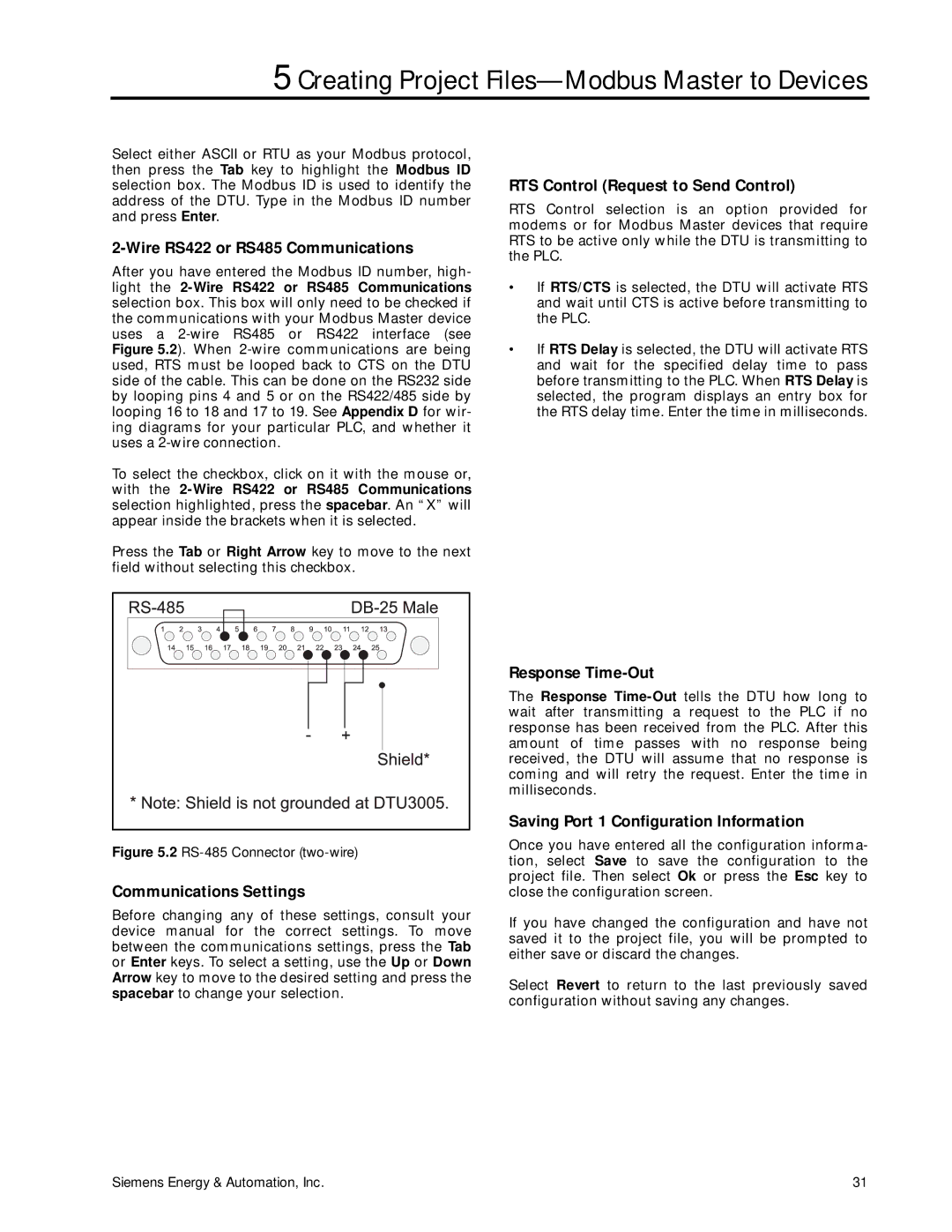
Figure 5.2 RS-485 Connector (two-wire)
Communications Settings
Before changing any of these settings, consult your device manual for the correct settings. To move between the communications settings, press the Tab or Enter keys. To select a setting, use the Up or Down Arrow key to move to the desired setting and press the spacebar to change your selection.
Response Time-Out
The Response
Saving Port 1 Configuration Information
Once you have entered all the configuration informa- tion, select Save to save the configuration to the project file. Then select Ok or press the Esc key to close the configuration screen.
If you have changed the configuration and have not saved it to the project file, you will be prompted to either save or discard the changes.
Select Revert to return to the last previously saved configuration without saving any changes.
Siemens Energy & Automation, Inc. | 31 |