2 Installing the SAMMS-MV Device
2.4.2 Grounding the Device
As stated in Guideline 5, ground each motor controller at a single ground point. The grounding path to earth must be permanent and continuous. It must also be able to safely conduct ground fault currents that may occur in the system to ground through minimum impedance. The earth ground does not carry any current under normal conditions.
Connect a ground bus to the chassis of each controller or to the chassis of the mounting equipment containing the earth ground through a grounding conductor.
Refer to Article 250 of the National Electrical Code for informa- tion about the types and sizes of wire conductors and methods for safely grounding electrical equipment and components.
Note: Do not ground the SAMMS auxiliary current sensor (ACT) leads. (See figure 2.1.)
2.4.3Connecting the Device to a Control Power Source
The
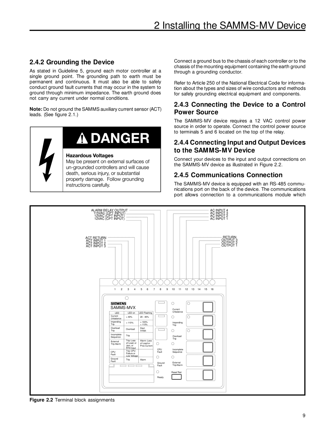
2.4.4Connecting Input and Output Devices to the SAMMS-MV Device
Connect your devices to the input and output connections on the
2.4.5 Communications Connection
The
ALARM RELAY OUTPUT |
|
|
|
|
|
|
|
|
|
|
|
|
|
| AC INPUT 4 | ||||||||||
|
|
|
|
|
|
|
|
|
|
|
|
|
| ||||||||||||
115VAC (CPT INPUT) |
|
|
|
|
|
|
|
|
|
|
|
|
|
|
| AC INPUT 3 | |||||||||
12VAC (CPT INPUT) |
|
|
|
|
|
|
|
|
|
|
|
|
|
| AC INPUT 2 | ||||||||||
12VAC (CPT INPUT) |
|
|
|
|
|
|
|
|
|
|
|
|
|
|
| AC INPUT 1 | |||||||||
ACT RETURN |
|
|
|
|
|
|
|
|
|
|
|
|
|
|
|
|
|
|
|
|
|
| RETURN | ||
|
|
|
|
|
|
|
|
|
|
| |||||||||||||||
ACT INPUT 1 |
|
|
|
|
|
|
|
|
|
|
|
|
|
|
|
|
|
|
|
| OUTPUT 3 | ||||
ACT INPUT 2 |
|
|
|
|
|
|
|
|
|
|
|
|
|
|
|
|
|
|
|
|
| OUTPUT 2 | |||
ACT INPUT 3 |
|
|
|
|
|
|
|
|
|
|
|
|
|
|
|
|
|
|
|
|
|
| OUTPUT 1 | ||
1 | 2 | 3 | 4 | 5 | 6 | 7 | 8 | 9 | 10 | 11 | 12 | 13 | 14 | 15 | 16 |
|
|
|
|
|
| Current |
|
|
|
|
| ||||
LED |
| LED on | LED Flashing |
|
|
| Unbalance |
|
|
|
|
| |||
|
|
|
|
|
|
|
|
|
|
| |||||
Current |
| > 40% |
| 20 - 40% |
|
|
|
|
|
|
|
|
|
| |
Unbalance |
|
|
|
|
|
|
|
|
|
|
| ||||
|
|
|
|
|
|
|
|
|
|
|
|
|
| ||
Impending | > 110% |
| > 100% |
|
|
| Impending |
|
|
|
|
| |||
Trip |
|
| < 110% |
|
|
|
|
|
|
|
| ||||
|
|
|
|
|
| Trip |
|
|
|
|
|
| |||
Overload |
| Overload | Start |
|
|
|
|
|
|
|
|
|
|
| |
Trip |
| Inhibit |
|
|
|
|
|
|
|
|
|
|
| ||
|
|
|
|
|
|
|
|
|
|
|
|
|
| ||
Incomplete | Trip |
|
|
|
|
|
| Overload |
|
|
|
|
| ||
Sequence |
|
|
|
|
|
|
|
|
|
|
|
| |||
|
|
|
|
|
|
|
|
|
|
|
|
| |||
|
|
|
|
|
|
|
| Trip |
|
|
|
|
|
| |
|
| Trip: Loss | Alarm: Loss |
|
|
|
|
|
|
|
|
| |||
External |
|
|
|
|
|
|
|
|
|
|
| ||||
| of Load, or | of Load or |
|
|
|
|
|
|
|
|
|
| |||
Trip Alarm |
|
|
|
|
|
|
|
|
|
|
| ||||
| Jam, or |
| Prcs Current |
|
|
|
|
|
|
|
|
|
| ||
|
|
|
|
|
|
|
|
|
|
|
|
| |||
|
| RTD Input |
|
|
| CPU |
| Incomplete |
|
|
|
|
| ||
|
| Trip: CPU |
|
|
|
|
|
|
|
|
| ||||
CPU |
|
|
|
| Fault |
| Sequence |
|
|
|
|
| |||
| Failure or |
|
|
|
|
|
|
|
|
| |||||
Fault |
|
|
|
|
|
|
|
|
|
|
|
|
| ||
| Low Voltage |
|
|
|
|
|
|
|
|
|
|
|
| ||
|
|
|
|
|
|
|
|
|
|
|
|
|
| ||
Ground |
| Trip |
| Alarm |
|
|
|
|
|
|
|
|
|
|
|
Fault |
|
|
|
|
|
|
|
|
|
|
|
|
| ||
|
|
|
|
|
| Ground |
| External |
|
|
|
|
| ||
|
|
|
|
|
|
|
|
|
|
|
|
| |||
|
|
|
|
|
|
| Fault |
| Trip/Alarm |
|
|
|
|
| |
|
|
|
|
|
|
|
|
| Reset/Test |
|
|
|
|
| |
|
|
|
|
|
|
| Ready |
|
|
|
|
|
|
|
|
Figure 2.2 Terminal block assignments
9