Appendix A Technical Specifications
Appendix A - Technical Specifications of the SAMMS-MV Device
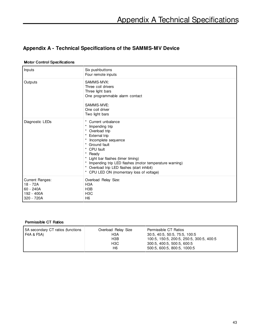
Motor Control Specifications |
|
|
|
| |
Inputs | Six pushbuttons | |
| Four remote inputs | |
Outputs | ||
| Three coil drivers | |
| Three light bars | |
| One programmable alarm contact | |
|
| |
| One coil driver | |
| Two light bars | |
Diagnostic LEDs | * | Current unbalance |
| * | Impending trip |
| * | Overload trip |
| * | External trip |
| * | Incomplete sequence |
| * | Ground fault |
| * | CPU fault |
| * | Ready |
| * | Light bar flashes (timer timing) |
| * | Impending trip LED flashes (motor temperature warning) |
| * | Overload trip LED flashes (start inhibit) |
| * | CPU LED ON (momentary loss of voltage) |
Current Ranges: | Overload Relay Size: | |
18 - 72A | H3A | |
60 - 240A | H3B | |
192 - 400A | H3C | |
320 - 720A | H6 | |
|
|
|
Permissible CT Ratios |
|
|
|
|
|
5A secondary CT ratios (functions | Overload Relay Size | Permissible CT Ratios |
F4A & F5A) | H3A | 30:5, 40:5, 50:5, 75:5, 100:5 |
| H3B | 100:5, 150:5, 200:5, 250:5, 300:5, 400:5 |
| H3C | 300:5, 400:5, 500:5, 600:5 |
| H6 | 500:5, 600:5, 800:5, 1000:5 |
|
|
|
43