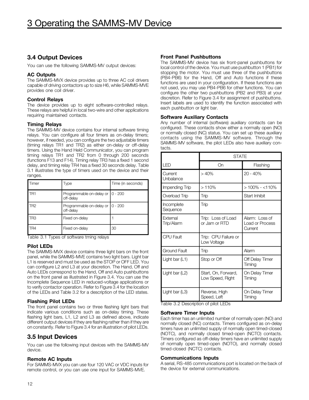
3.4 Output Devices
You can use the following SAMMS-MV output devices:
AC Outputs
The SAMMS-MVX device provides up to three AC coil drivers capable of driving contactors up to size H6, while SAMMS-MVE provides one coil driver.
Control Relays
The device provides up to eight software-controlled relays. These relays are helpful in local two-wire and other applications requiring maintained contacts.
Timing Relays
The SAMMS-MV device contains four internal software timing relays. You can configure all four timers as on-delay timers; however, if needed, you can configure the two adjustable timers (timing relays TR1 and TR2) as either on-delay or off-delay timers. Using the Hand Held Communicator, you can program timing relays TR1 and TR2 from 0 through 200 seconds (functions F13 and F14). Timing relay TR3 has a fixed 1 second delay, and timing relay TR4 has a fixed 30 seconds delay. Table
3.1illustrates the type of timers used on the device and their ranges.
Timer | Type | Time (in seconds) |
| | |
TR1 | Programmable on-delay or | 0 - 200 |
| off-delay | |
| | |
TR2 | Programmable on-delay or | 0 - 200 |
| off-delay | |
| | |
TR3 | Fixed on-delay | 1 |
| | |
TR4 | Fixed on-delay | 30 |
Table 3.1 Types of software tming relays
Pilot LEDs
The SAMMS-MVX device contains three light bars on the front panel, while the SAMMS-MVE contains two light bars. Light bar L1 is reserved and must be used as the STOP or OFF LED. You can configure L2 and L3 at your discretion. The Hand, Off and Auto LEDs correspond to the Hand, Off and Auto pushbuttons on the front panel as illustrated in Figure 3.4. You can use the Incomplete Sequence LED in reduced-voltage applications or to verify contactor operation. Refer to Figure 3.4 for the location of the LEDs and Table 3.2 for a description of the LED states.
Flashing Pilot LEDs
The front panel contains two or three flashing light bars that indicate various conditions such as on-delay timing. These flashing light bars, L1, L2 and L3 as defined above, indicate different output devices if they are flashing rather than if they are on constantly. Refer to Figure 3.4 for an illustration of pilot LEDs.
3.5 Input Devices
You can use the following input devices with the SAMMS-MV device.
Remote AC Inputs
For SAMMS-MVX you can use four 120 VAC or VDC inputs for remote control, or you can use one input for SAMMS-MVE.
Front Panel Pushbuttons
The SAMMS-MV device has six front-panel pushbuttons for local control of the device. You must use pushbutton 1 (PB1) for stopping the motor. You must use three of the pushbuttons (PB4-PB6) for the Hand, Off and Auto functions if these functions are used in your configuration. If these functions are not used, you may use PB4-PB6 for other functions. You can configure the other two pushbuttons (PB2 and PB3) at your discretion. Refer to Figure 3.4 for assignment of pushbuttons. Insert labels are used to identify the function associated with each pushbutton or light bar.
Software Auxiliary Contacts
Any number of internal (software) auxiliary contacts can be configured. These contacts show either a normally open (NO) or normally closed (NC) status. You can set up these auxiliary contacts using the SAMMS-MV software. Through the SAMMS-MV software, the pilot LEDs also have auxiliary con- tacts.
| STATE |
| | |
LED | On | Flashing |
| | |
Current | > 40% | 20 - 40% |
Unbalance | | |
| | |
Impending Trip | > 110% | > 100% - <110% |
| | |
Overload Trip | Trip | Start Inhibit |
| | |
Incomplete | Trip | |
Sequence | | |
| | |
External | Trip: Loss of Load | Alarm: Loss of |
Trip/Alarm | or Jam or RTD | Load or Process |
| | Current |
| | |
CPU Fault | Trip: CPU Failure or | |
| Low Voltage | |
| | |
Ground Fault | Trip | Alarm |
| | |
Light bar (L1) | Stop or Off | Off Delay Timer |
| | Timing |
| | |
Light bar (L2) | Start, On, Forward, | On Delay Timer |
| Low Speed, Right | Timing |
| | |
Light bar (L3) | Reverse, High | On Delay Timer |
| Speed, Left | Timing |
Table 3.2 Description of pilot LEDs
Software Timer Inputs
Each timer has an unlimited number of normally open (NO) and normally closed (NC) contacts. Timers configured as on-delay timers have an unlimited supply of normally open timed-closed (NOTC), and normally closed timed-open (NCTO) contacts. Timers configured as off-delay timers have an unlimited supply of normally open timed-open (NOTO), and normally closed timed-closed (NCTC) contacts.
Communications Inputs
A serial, RS-485 communications port is located on the back of the device for external communications.

